
Hitachi HD44780 based 16x2 character LCD are very cheap and widely available, and is a essential part for any projects that displays information. Using the I2C bus on Raspberry Pi ,PCF8574 IC, and Python characters/strings can be displayed on the LCD. The PCF8574 is an general purpose bidirectional 8 bit I/O port expander that uses the I2C protocol.
The LCD(HD44780) is connected in 4 bit mode as follows to the PCF8574:-

P0 - D4
P1 - D5
P2 - D6
P3 - D7
P4 - RS
P5 - R/W
P6 - E
Port A0 is connected to VCC(5V) with a 10k resistor so that it will be addressed at 0x21.


import smbus
from time import *
# General i2c device class so that other devices can be added easily
class i2c_device:
 def __init__(self, addr, port):
  self.addr = addr
  self.bus = smbus.SMBus(port)
 def write(self, byte):
  self.bus.write_byte(self.addr, byte)
 def read(self):
  return self.bus.read_byte(self.addr)
 def read_nbytes_data(self, data, n): # For sequential reads > 1 byte
  return self.bus.read_i2c_block_data(self.addr, data, n)
class lcd:
 #initializes objects and lcd
 '''
 Reverse Codes:
 0: lower 4 bits of expander are commands bits
 1: top 4 bits of expander are commands bits AND P0-4 P1-5 P2-6
 2: top 4 bits of expander are commands bits AND P0-6 P1-5 P2-4
 '''
 def __init__(self, addr, port, reverse=0):
  self.reverse = reverse
  self.lcd_device = i2c_device(addr, port)
  if self.reverse:
   self.lcd_device.write(0x30)
   self.lcd_strobe()
   sleep(0.0005)
   self.lcd_strobe()
   sleep(0.0005)
   self.lcd_strobe()
   sleep(0.0005)
   self.lcd_device.write(0x20)
   self.lcd_strobe()
   sleep(0.0005)
  else:
   self.lcd_device.write(0x03)
   self.lcd_strobe()
   sleep(0.0005)
   self.lcd_strobe()
   sleep(0.0005)
   self.lcd_strobe()
   sleep(0.0005)
   self.lcd_device.write(0x02)
   self.lcd_strobe()
   sleep(0.0005)
  self.lcd_write(0x28)
  self.lcd_write(0x08)
  self.lcd_write(0x01)
  self.lcd_write(0x06)
  self.lcd_write(0x0C)
  self.lcd_write(0x0F)
 # clocks EN to latch command
 def lcd_strobe(self):
  if self.reverse == 1:
   self.lcd_device.write((self.lcd_device.read() | 0x04))
   self.lcd_device.write((self.lcd_device.read() & 0xFB))
  if self.reverse == 2:
   self.lcd_device.write((self.lcd_device.read() | 0x01))
   self.lcd_device.write((self.lcd_device.read() & 0xFE))
  else:
   self.lcd_device.write((self.lcd_device.read() | 0x10))
   self.lcd_device.write((self.lcd_device.read() & 0xEF))
 # write a command to lcd
 def lcd_write(self, cmd):
  if self.reverse:
   self.lcd_device.write((cmd >> 4)<<4 0x0f="" cmd="" else:="" self.lcd_device.write="" self.lcd_strobe="" x0="">> 4))
   self.lcd_strobe()
   self.lcd_device.write((cmd & 0x0F))
   self.lcd_strobe()
   self.lcd_device.write(0x0)
 # write a character to lcd (or character rom)
 def lcd_write_char(self, charvalue):
  if self.reverse == 1:
   self.lcd_device.write((0x01 | (charvalue >> 4)<<4 0x0f="" 2:="" charvalue="" if="" self.lcd_device.write="" self.lcd_strobe="" self.reverse="=" x01="" x04="" x0="">> 4)<<4 0x0f="" charvalue="" else:="" self.lcd_device.write="" self.lcd_strobe="" x04="" x0="" x40="">> 4)))
   self.lcd_strobe()
   self.lcd_device.write((0x40 | (charvalue & 0x0F)))
   self.lcd_strobe()
   self.lcd_device.write(0x0)
 # put char function
 def lcd_putc(self, char):
  self.lcd_write_char(ord(char))
 # put string function
 def lcd_puts(self, string, line):
  if line == 1:
   self.lcd_write(0x80)
  if line == 2:
   self.lcd_write(0xC0)
  if line == 3:
   self.lcd_write(0x94)
  if line == 4:
   self.lcd_write(0xD4)
  for char in string:
   self.lcd_putc(char)
 # clear lcd and set to home
 def lcd_clear(self):
  self.lcd_write(0x1)
  self.lcd_write(0x2)
 # add custom characters (0 - 7)
 def lcd_load_custon_chars(self, fontdata):
  self.lcd_device.bus.write(0x40);
  for char in fontdata:
   for line in char:
    self.lcd_write_char(line)
Main Program:-
import pylcdlib
lcd = pylcdlib.lcd(0x21,0)
lcd.lcd_puts("Raspberry Pi",1)  #display "Raspberry Pi" on line 1
lcd.lcd_puts("  Take a byte!",2)  #display "Take a byte!" on line 2
Save the above code as test_lcd.py and enter sudo python test_lcd.py
My code assumes that the first 4 bits of the LCD(11,12,13,14) are connected to P0,P1,P2,P3 ports on PCF8574. The next 3 ports on PCF8574(P4,P5,P6) should be connected to 4-RS, 5-R/W, 6-E.However there are other serial backpack lcd's with different pinouts. According to the wiring of your serial backpack LCD you can override the default mapping during initialization.There are 3 modes available-
lcd = pylcdlib.lcd(0x21,0) lower 4 bits of expander are commands bits
lcd = pylcdlib.lcd(0x21,0,1) top 4 bits of expander are commands bits AND P0-4 P1-5 P2-6
lcd = pylcdlib.lcd(0x21,0,2) top 4 bits of expander are commands bits AND P0-6 P1-5 P2-4
(Update):- If you have a Raspberry Pi with a revision 2.0 board, you need to use I²C bus 1, not bus 0, so you will need to change the bus number used. In this case, the line lcd = pylcdlib.lcd(0x21,0) would become lcd = pylcdlib.lcd(0x21,1).
You can check that the device is present on the bus by using the i2cdetect program from the i2ctools package-
i2cdetect 0 -y or i2cdetect 1 -y
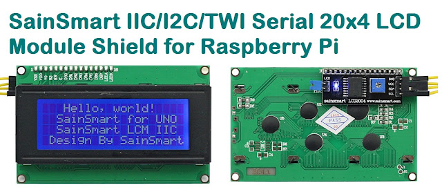
Compatible LCD Module for this article:-

Thanks a lot, will be using this in my next project
ReplyDelete:)
ReplyDeleteHello, when I run:
ReplyDeletepython main.py
Show this error:
Traceback (most recent call last):
File "main.py", line 2, in
lcd=pylcd2.lcd(0x21,0,2)
NameError: name 'pylcd2' is not defined
[email protected] ~/lcd $
Note:
[email protected] ~/lcd $ ls
main.py pylcdlib.py pylcdlib.pyc
I have this lcd:
http://www.bcncybernetics.com/I2C_TWI_LCD1602_Module_p/dfr-0063.htm
Thanks a lot!
Oscar.
Fixed the problem.Should work now.
ReplyDeleteOk, thanks Rahul, I see the "lcd=pylcdlib.lcd(0x21,2)" fixed.
ReplyDeleteBut now I have another problem...
When I run:
python main.py
Show me this:
Traceback (most recent call last):
File "main.py", line 2, in
lcd=pylcdlib.lcd(0x21,2)
File "/home/pi/lcd/pylcdlib.py", line 18, in __init__
self.lcd_device=i2c_dev(addr,port)
File "/home/pi/lcd/pylcdlib.py", line 7, in __init__
self.bus=smbus.SMBus(port)
IOError: [Errno 2] No such file or directory
I think the problem is something about port.
I have my RPi conected like that:
http://imageshack.us/photo/my-images/338/lcdrpi01.jpg/
http://imageshack.us/photo/my-images/198/lcdrpi02.jpg/
http://imageshack.us/photo/my-images/210/lcdrpi03.jpg/
My RPi have the Adafruit Prototyping Pi Plate :
http://www.adafruit.com/images/medium/ID801_MED.jpg
Hi Oscar,I checked your images and noticed that you are using an I2C based LCD display.It should use an PCF8574 IC for this code to work in your case.
ReplyDeleteAnd regarding that IOError did you execute the command using sudo?try using "i2cdetect -y 0" to check which port it is using.
I'm trying to connect and LCD with I2c Interface to raspbery, but I can't.
ReplyDeleteCan I use this example with this LCD? when i execute, the LCD turn on and turn off, but nothing.
Hi Oscar,Rahul,
ReplyDeleteI have the same display and problem.the i2c adress is 0x27.
Do you solve your problem?
I found a error, in the program I put the 0 port instead the 2. owever the LED goes on and off, but shows no character
ReplyDeleteTry this.... http://www.rpiblog.com/2012/11/interfacing-16x2-lcd-with-raspberry-pi.html
ReplyDeleteUses only 6 GPIO pins to interface with LCD
Thanks, but my LCD have an I2C adapter and i can't use with this configuration :( I need to use with I2C!
ReplyDeleteIs your LCD module using PCF8574 or some other IC?
ReplyDeleteMy Lcdmodul use a pca8574
ReplyDeletehi Mike,looks like your lcd uses a different pinout,so I have added 3 different modes.Trace your wiring and determine which mode is required and override the initialization accordingly.Also make sure the address is correct.As you have mentioned earlier the i2c address was 0x27,so the A1,A2,A3 inputs of PCF8574 must be connected to VCC.
ReplyDeleteMy lcd uses the PFC8574. Nothing of your update still work for me, it's no necesary use a level converte to 5v of LCD and 3v3 of Raspberry?
ReplyDeleteI just check my connection between LCD an PCF8574, How can I put in the code the correct order?
ReplyDeleteP0 -> RS
P1 -> R/W
P2 -> E
P4 - > DB4
P5 -> DB5
P6 -> DB6
P7 -> DB7
You need to replace lcd = pylcdlib.lcd(0x21,0) with lcd = pylcdlib.lcd(0x21,0,1) in the main program.Also check the connection of A1,A2,A3 pins/i2c address..
ReplyDeleteHi Rahul,
ReplyDeletei have the following error:
Traceback (most recent call last):
File "main.py", line 1, in
import pylcdlib
File "/home/pi/i2c/python/pylcdlib.py", line 1
import smbus
^
IndentationError: unexpected indent
i have installed the latest version of python-smbus correctly..
Hi Rahul,
ReplyDeleteforget my last Post (read first, then ask) ;-)
it runs !
Hi Rahul,
ReplyDeleteThank you for the article, helped me a lot.
Prokop of the Czech Republic
Is this code also working on a 4*20 lcd HD44780 PCF8574
ReplyDeleteYour project is nice, but is it not RPi compliant. You need to use level conversion for the I2C lines, or can damage the RPi boaard : http://elinux.org/RPi_Low-level_peripherals#General_Purpose_Input.2FOutput_.28GPIO.29
ReplyDeleteYou can use Mosfets for I2C level conversion.
Thats not complete true, they have made special in rev.2 2 pins for the I2C lines and therefore its no problem to use these.
DeleteThe only thing you just have to watch out is the power suply, so the best way is to use a external power suply.
Any chance of an update for a 20x4 and http://www.adafruit.com/products/292 ?
ReplyDeleteWith some help of the logic analyzer the code works finally!!!!.
ReplyDeleteCheck you i2c bus expander if you have an a or normal version.
This will change the address
Also the e rs and the pin should be reversed.
so e --> P4
and rs --> P6
Kind Regards
Arjan
Hi!
ReplyDeletePlease select a different program 4x20 LCD control!
Thank you very much!
Sorry for the bad english: (
Hi everybody!
ReplyDeleteI would like to print an integer, is there a way to do it?
I'm using this script with a 20x4 lcd.
Debolman
Hi Debolman,
ReplyDeleteJust place your integer as string like.:
lcd.lcd_puts("This is a integer "+ str(1),4)
hello
ReplyDeleteany solutions for an display with contrast?
thanks
Is there a way to switch off the backlight for powersaving reasons?
ReplyDeleteadd this code
Deletelcd.lcd_device.write(0x00)
nice. thanx!!
ReplyDeleteThank you Rahul, your code work's well with my 16x2 LCD. I just had to switch the E and RS Pin. Today I tried to get the 20x4 LCD running, so I connected it with the PCF8574 the same way it's in your schematic, but also with switched E and RS. But if I run the script (wich is working for 16x2) only the Cursor is blinking in one position, but there's no text. Also tried to switch E and RS again, but then the screen is full of cryptic text. Can you give me a hint? Perhaps i have to change something in the code? Regards
ReplyDeleteSPI and I2C is disabled on PI by default. Go here
ReplyDeletesudo vim /etc/modprobe.d/raspi-blacklist.conf
and uncomment the line with i2c
reboot
Just found a bug in your code. lines 66 and 96 should be elif statements and not if statements. Produces rubbish if reverse=1
ReplyDeletePerfect, doing those 2 line fixes and replacign if with elif works magic.
DeleteHowever, I am not able to control the Back light. This is one of the kits based on the PCF8574 which are very cheap, and you can solder them directly to the LCD solder holes.
The Kit works well on Arduino including backlight control, but in Pi, the backlight just flashes and goes off. The text is coming properly after the elif changes you mentioned. Any idea, where to change the backlight control ?
Yep! I confirm it too! When fixed the code based on Rob's Colez post - all works perfect now! Thanks to all!
ReplyDelete