
By using the Raspberry Pi Compute Module, the platform is fully compatible with existing Raspberry Pi ecosystem. This in turn will allow you to leverage the seemingly endless libraries of code, application notes and peripherals that are already available.
Product Features:
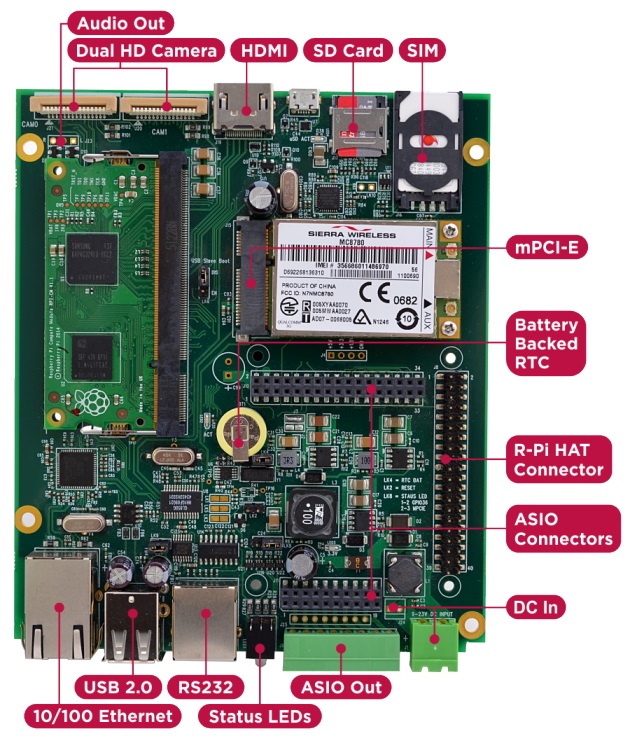
· Integrated 10/100 Ethernet Adapter
· Dual High-Resolution Raspberry Pi Camera Interfaces
· Mini PCI-E Interface + SIM connector
· High Speed SD compliant Micro SD Card interface
· ASIO Connectors allowing more comprehensive Application Specific solutions
· Raspberry Pi 2 HAT Compatible I/O Connector & Mounting Points (4 x M2.5)
· Independent USB UART (RX/TX/RTS/CTS)
· HDMI Out
· 8Way 2 part 3.5mm Phoenix industrial connector for use with ASIO Outputs or HAT board
· Integrated battery backed Real-Time-Clock (RTC)
· 2 x Bi-Colour (Red/Green) front panel status LEDs
· Wide 7-23V (poly-fused and filtered) High capacity DC power input via either 2 part Phoenix screw terminal front panel connector or internal 2way Molex AM254 Connector
HAT Compatible
Because the platform uses a standard HAT connector it's also backwards compatible with RPi HAT boards that you may already have or want to use, even allowing you to bring HAT IO connectivity out of the front using the industrial connector.
I/O Cards
In order to retain flexibility for various different IO configurations they have opted to use I/O connector in, instead of the actual I/O. So instead of plugging in HAT card with I/O signal connectors poking out on all sides, they have these same I/O signals back down a second output connector which is directly connected to the green industrial connector.
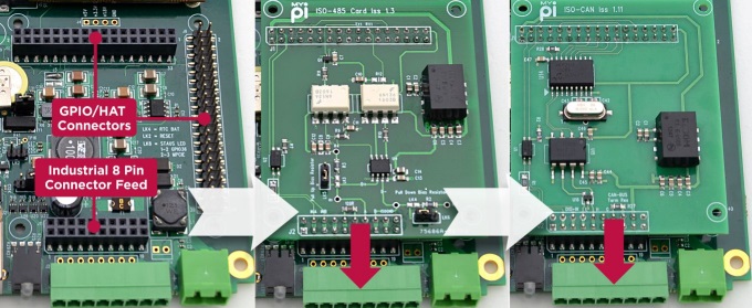
The added bonus here is that by simply using extended length interface pins on the card (raising it up) you can expand the IO set further - all without using any cable assemblies! They have pre-designed a series of hardened plug in cards for dealing common applications like CAN-Bus, 4-20mA transducer signals, RS485, Narrow Band RF and others. This way you have to spend less time dealing with hardware and more time focusing on software development.
Enclosure Design
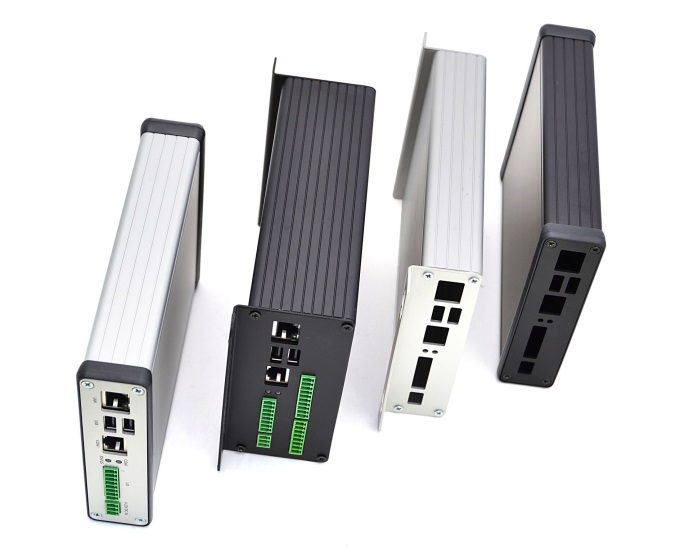
The best thing about their enclosure type is that they require only the end plates to be punched to match the board connectors, which reduces the design and manufacturing costs involved significantly. The PCB features 4 mounting holes, making it easy to install inside a larger or custom enclosure design if required.
The enclosure comes in two sizes, a low profile version and a larger double height model allowing extra room. All the single function I/O cards designed have been built with the lowest profile enclosure type in mind allowing for a neat solution.
Head over to Kickstarter to read more or to back the campaign.
Head over to Kickstarter to read more or to back the campaign.
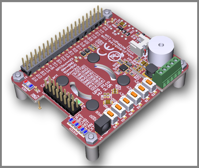
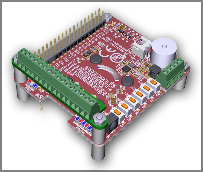
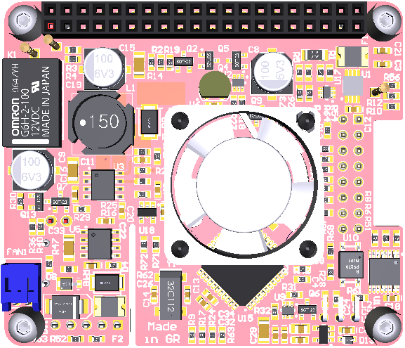
It is specially designed for the Raspberry Pi® 3 but it's also compatible with all other models. It comes equipped with 3 User Keys, 3 User LEDs, 3 different types of high capacity batteries, 2 x 3 pins bi-stable relay (Zero Power), as also 3 x A/D 12 bit converters pre-adjusted to 5V, 15V and 30V conversion.
Power Specifications:
Pimodules have implemented a Dynamic Power Tracking feature that can automatically adjust battery charging current according to power availability ranging from 50mA - 1000 mAh. This feature has been especially designed to support Solar Panel Powering Raspberry Pi® Systems, as the output from solar panel can vary according to weather conditions. UPS PIco HV3.0A can accept external voltage input ranging from 7 V DC up to 28 V DC !! This makes it ideal for use in Cars, Trucks, Buses and any industrial applications where voltage is usually higher than 24V DC. The External Supply Powering Input is equipped with Over Current protection, Over Voltage as also with Zero Voltage Drop Inverse Polarity Protection in order to use all available energy from the solar panel.
Product Overview:
The UPS PIco HV3.0A is equipped with a standard 450 mAh 15C LiPO battery specially designed to enable safe shutdown during mains power failure. The included battery provides enough power to keep running the system for 5-8 minutes. Additionally, you can also upgrade the battery capacity to 4000mAh, 8000 mAh or 12000 mAh batteries (optional on special request). With 12000 mAh batteries on board, you can use your Raspberry Pi for more than 32 hours without a power supply connected!
The UPS PIco HV3.0A 450 mAh Stack Plus design supports 2 types of lithium cell chemistry: LiPO as also LiFePO4. LiFePO4 batteries are useful in applications where temperature environment is more restricted which can range from -10 degrees up to +60 degrees. In addition, the LiFePO4 chemistry offers a longer cycle life than other lithium-ion cells out there. It can achieve up to 2000 cycles!!
Peripherals
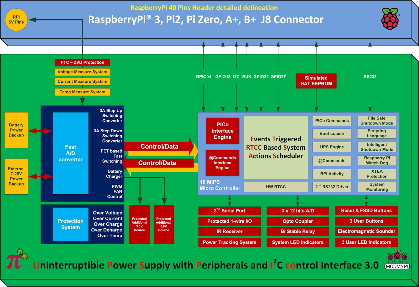
1. RTCC: UPS PIco HV3.0A comes with a integrated Hardware Real Time Clock and Calendar, which keeps time even when the system is running without access to the Network. The Hardware RTCC is backed up and powered from the integrated system battery. The RTCC current consumption is only 1 uA. The integrated Hardware RTCC enables a new extremely usefully feature - the Events Triggered RTCC Based System Actions Scheduler. The Events Triggered RTCC Based System Actions Scheduler allows to timely start up, or shutdown the Raspberry Pi® on various internal or external events that include, 1-wire, IR, A/D, RTCC, temperature, Opto Coupled Input or just on requested Time Stamp.
3. Monitoring: You can now monitor high voltage signals safely with the Opto Coupled interface, which can be read as digital or as analogue input. It's 12 bit buffered A/D comes with built-in ESD protection. In addition, you can monitor system health such as Battery Voltage, External Powering Voltage, Raspberry Pi Voltage, Current Consumption, System Temperature and 1-wire interface.
4. IR Receiver: The UPS PIco HV3.0A can also be equipped with an optional Infra-Red Receiver which is routed directly to GPIO18 via the PCB. This opens the door for remote operation of the Raspberry Pi® and UPS Pico!
5. Sound Transducer: The embedded Electromagnetic Programmable Sounder can be used as a simple buzzer but also as music player due to implemented sound generator and dedicated programmer interface.
6. Secondary Serial Port: With UPS PIco HV3.0A you can have access to a integrated secondary serial port which is compatible with both 3.3V & 5V TTL logic level. When used with Terminal Block it can support up-to 12V TTL logic level conversion. Their software driver is under development and will be delivered within 1 month after system delivery.
7. LEDS: UPS PIco HV3.0A comes with six independent LED's to inform user about system status.
Finally, the UPS PIco HV3.0A features an Automatic Temperature Control PWM FAN controller, and can be equipped with a micro fan kit, which enables the use of the Raspberry Pi® in extreme conditions including very high temperature environments. The FAN speed is automatically adjusted according to system temperature conditions semi linearly (8 levels) from 0 % (FAN is OFF) up to 100% by increasing and decreasing rotation speed. This guarantees a always cool Raspberry Pi® with low noise level.
Technical Specifications:
Product Comparison Table: UPS PIco HV3.0A_Product_Comparison.pdf

It lets you develop science and electronics experiments, demonstrations, and projects without getting too involved in the nitty-gritty details of electronics or computer programming. In other words it basically converts your Raspberry Pi into a portable science and electronics laboratory.
Features:
● 12 bit Analog Input/Output
● Digital I/O
● Time interval measurements
● Waveform Generation
● USB Powered
● GUI for 50 experiments
● Python Programmable
● Works as a Test Equipment
● 8.6 x 5.8 x 1.5 cm3, 60 gm.
● Open Hardware
expEYES is powered by an AVR ATmega16 MCU , running at 8 MHz. It uses FT232RL chip to communicate with the Raspberry Pi. expEYES is capable of acting as a four-channel oscilloscope with 12-bit analogue resolution, microsecond timing resolution and a 250 kHz sampling frequency. It also comes equipped with an built-in signal generator.
Interfacing with Raspberry Pi
First, update your system's package list by entering the following command in LXTerminal or from the command line:
sudo apt-get update
Next, run the following command
sudo apt-get install expeyes
ExpEYES has a number of dependencies that are required for it to run under Linux, as well as a number of other recommended libraries. To avoid any problems later, you can run the following command in order to make sure that they are all installed:
sudo apt-get install python python-expeyes python-imaging-tk python-tk grace tix python-numpy python-scipy python-pygrace
expEYES Hardware Availability
ExpEYES is currently available from the following firms:-
- Fab.to.Lab (Ships Internationally) (Cheapest Online)
- Pi-Supply (Ships Internationally)
The UniPi board is designed to fit on the cheap and easy to use Raspberry Pi mini computer. If has 8 changeover relays, 14 digital inputs, single channel 1-wire interface, 2 analog inputs 0-10V and one analog 0-10V output. Furthermore the second I2C port of the RPi features 5V level converter and ESD protection, so you can easily connect other devices. The same applies to the UART!
 https://www.indiegogo.com/projects/unipi-the-universal-raspberry-pi-add-on-board
Does it have anything else that might be usable? Of course! It has Real Time Clock module so if your Pi looses power, the clock stays synced so when the system comes up, it will do everything as planned.
UniPi features:
- 8 relays
- 14 digital inputs
- 1Wire controller
- 2 analog inputs
- 1 analog output
- Real time clock
- EEPROM
What does it make?
Cool! So it has many ways to communicate with the real world. But what can I use it for?
Relays - The UniPi has 8 changeover relays which are able to switch up to 5A @ 230V. With that much power, you can easily switch lights, open doors and garage doors, control motors and many other cool stuff.
Digital Inputs - All of the 14 digital inputs of the UniPi is connected directly to the Raspberry Pi GPIO through an opto-isolation. With this, you can easily read 5-20V signals from your window sensors, alarm sensors, count consumption of your energy meters and basically everything that closes/opens contact. In addition to this the board has 12V power supply for easy input state reading so you don't need to buy expensive power supplies. Just use the one we've already provided!
Analog Inputs - Do you need to know, what power is certain device working at? Simple connect its 0-10V output to the UniPi and you are done!
Analog Output - But what if you need to control the performance of a device? Well we have solution even for this. With the analog 0-10V output, you can easily control output power of many different devices, such as motors, frequency changes,...
1Wire - And what about temperature? Can the UniPi read temperature? Of course! It features single channel 1wire interface so you can connect up to hundred of sensors to measure temperature and humidity!

Numato’s 8 Channel Bluetooth GPIO module is low cost easily deployable solution for connecting your PC to other electronic circuitry through Bluetooth. A USB Bluetooth Dongle or Bluetooth integrated PC/Laptop would be sufficient to communicate with this device. 8 TTL compatible GPIOs available and 6 Analog input channels (shared with GPIOs). 10 Bit Analog input resolution. All GPIOs can be individually configured as input or output. 20ma Source/Sink capacity per IO.
Link For Product: http://numato.cc/content/freebie-week-8-channel-bluetooth-gpio-module
Unfortunately all the 17 pins of Raspberry Pi are digital which can either output HIGH or LOW. But by using a simple circuit (poor man's A/D converter) you can measure multiple level of values using a single GPIO pin. It consists of a basic “RC” charging circuit in which a Resistor in placed series with a Capacitor. The voltage across the capacitor rises when voltage is applied across the RC network. Using the formula [t = RC ] where t is the time,R is resistance in ohms,and C is capacitance in Farads and the time taken to register a HIGH on a GPIO pin we can roughly estimate the analog value.
Algorithm:-
Step 1: Set any GPIO pin as an output and set it Low.This ensures that no charge is present in capacitor and both the terminals are at 0V.
Step 2: Now set the GPIO pin as an input.This will starts a flow of current through the resistors and through the capacitor to ground. The voltage across the capacitor starts to rise. The time taken will be proportional to the input.
Step 3: Read the value from GPIO pin and keep incrementing a counter variable until the value is LOW.
Step 4: At some point the value from GPIO will register a HIGH. When it does return the value of the counter.
Step 5: Set the GPIO pin as an output and repeat the process as required.
Python Implementation:-
Example Circuit:-

Note:- The above technique will only work with sensors that act like resistors like photocells, thermistors, flex sensors, force-sensitive resistors, etc.
It cannot be used with sensors that have a pure analog output like IR distance sensors or analog accelerometers.
Source:- Adafruit
Algorithm:-
Step 1: Set any GPIO pin as an output and set it Low.This ensures that no charge is present in capacitor and both the terminals are at 0V.
Step 2: Now set the GPIO pin as an input.This will starts a flow of current through the resistors and through the capacitor to ground. The voltage across the capacitor starts to rise. The time taken will be proportional to the input.
Step 3: Read the value from GPIO pin and keep incrementing a counter variable until the value is LOW.
Step 4: At some point the value from GPIO will register a HIGH. When it does return the value of the counter.
Step 5: Set the GPIO pin as an output and repeat the process as required.
Python Implementation:-
#!/usr/local/bin/python
# GPIO   : RPi.GPIO v3.1.0a
import RPi.GPIO as GPIO
import time
GPIO.setmode(GPIO.BCM)
# Define function to measure charge time
def RC_Analog (Pin):
  counter = 0
  # Discharge capacitor
  GPIO.setup(Pin, GPIO.OUT)
  GPIO.output(Pin, GPIO.LOW)
  time.sleep(0.1)
  GPIO.setup(Pin, GPIO.IN)
  # Count loops until voltage across capacitor reads high on GPIO
  while(GPIO.input(Pin)==GPIO.LOW):
        counter =counter+1
  return counter
# Main program loop
while True:
  print RC_Analog(4) # Measure timing using GPIO4
Example Circuit:-

Note:- The above technique will only work with sensors that act like resistors like photocells, thermistors, flex sensors, force-sensitive resistors, etc.
It cannot be used with sensors that have a pure analog output like IR distance sensors or analog accelerometers.
Source:- Adafruit
7 segments can be driven using many different techniques in conjunction with software and hardware. Multiplexing is one of the most popular methods used to drive a 7 segment display when there are limited no of I/O pins.It uses the concept of POV(persistence of vision) where the human brain cannot detect the flickering of display when the refresh rate is very high(~50Hz).In this method the fundamental logic is to enable or disable the segment blocks at a very high speed at precise time slices.
 In case of Raspberry Pi there are limited no of I/O pins, hence we will use multiplexing. WiringPi is perfect for this job as it uses Arduino like code and the code executes at a higher priority. Display used in this example is of common cathode type.Make sure you have the right 7 segment display,else you will end up getting random segments turned on.For pin mapping check the code below:-
Compile the code as...
gcc -o display segment.c -L/usr/local/lib -lwiringPi
Now execute it...
sudo ./display

Code:-
#include <wiringPi.h>
#include <stdio.h>
#define DISPLAY_BRIGHTNESS  500
#define DIGIT_ON  HIGH
#define DIGIT_OFF  LOW
#define SEGMENT_ON  LOW
#define SEGMENT_OFF HIGH
int SEGMENT_1=7;
int SEGMENT_2=11;
int SEGMENT_3=13;
int SEGMENT_4=15;
int SEGMENT_A=3;
int SEGMENT_B=5;
int SEGMENT_C=18;
int SEGMENT_D=19;
int SEGMENT_E=23;
int SEGMENT_F=24;
int SEGMENT_G=25;
void display_number(int num)
{
  pinMode(SEGMENT_1,OUTPUT);
  pinMode(SEGMENT_2,OUTPUT);
  pinMode(SEGMENT_3,OUTPUT);
  pinMode(SEGMENT_4,OUTPUT);
  long start=millis();
  for(int i=4;i>0;i--)
  {
    switch(i)
    {
    case 1:
      digitalWrite(SEGMENT_1,DIGIT_ON);
      break;
    case 2:
      digitalWrite(SEGMENT_2,DIGIT_ON);
      break;
    case 3:
      digitalWrite(SEGMENT_3,DIGIT_ON);
      break;
    case 4:
      digitalWrite(SEGMENT_4,DIGIT_ON);
      break;
    }
    print_number(num%10);
    num/=10;
    delayMicroseconds(DISPLAY_BRIGHTNESS);
    print_number(10);
    digitalWrite(SEGMENT_1,DIGIT_OFF);
    digitalWrite(SEGMENT_2,DIGIT_OFF);
    digitalWrite(SEGMENT_3,DIGIT_OFF);
    digitalWrite(SEGMENT_4,DIGIT_OFF);
  }
  while((millis()-start)<10);
}
void print_number(int num)
{
  pinMode(SEGMENT_A,OUTPUT);
  pinMode(SEGMENT_B,OUTPUT);
  pinMode(SEGMENT_C,OUTPUT);
  pinMode(SEGMENT_D,OUTPUT);
  pinMode(SEGMENT_E,OUTPUT);
  pinMode(SEGMENT_F,OUTPUT);
  pinMode(SEGMENT_G,OUTPUT);
  switch(num)
  {
  case 0:
    digitalWrite(SEGMENT_A,SEGMENT_ON);
    digitalWrite(SEGMENT_B,SEGMENT_ON);
    digitalWrite(SEGMENT_C,SEGMENT_ON);
    digitalWrite(SEGMENT_D,SEGMENT_ON);
    digitalWrite(SEGMENT_E,SEGMENT_ON);
    digitalWrite(SEGMENT_F,SEGMENT_ON);
    digitalWrite(SEGMENT_G,SEGMENT_OFF);
    break;
  case 1:
    digitalWrite(SEGMENT_A,SEGMENT_OFF);
    digitalWrite(SEGMENT_B,SEGMENT_ON);
    digitalWrite(SEGMENT_C,SEGMENT_ON);
    digitalWrite(SEGMENT_D,SEGMENT_OFF);
    digitalWrite(SEGMENT_E,SEGMENT_OFF);
    digitalWrite(SEGMENT_F,SEGMENT_OFF);
    digitalWrite(SEGMENT_G,SEGMENT_OFF);
    break;
  case 2:
    digitalWrite(SEGMENT_A,SEGMENT_ON);
    digitalWrite(SEGMENT_B,SEGMENT_ON);
    digitalWrite(SEGMENT_C,SEGMENT_OFF);
    digitalWrite(SEGMENT_D,SEGMENT_ON);
    digitalWrite(SEGMENT_E,SEGMENT_ON);
    digitalWrite(SEGMENT_F,SEGMENT_OFF);
    digitalWrite(SEGMENT_G,SEGMENT_ON);
    break;
  case 3:
    digitalWrite(SEGMENT_A,SEGMENT_ON);
    digitalWrite(SEGMENT_B,SEGMENT_ON);
    digitalWrite(SEGMENT_C,SEGMENT_ON);
    digitalWrite(SEGMENT_D,SEGMENT_ON);
    digitalWrite(SEGMENT_E,SEGMENT_OFF);
    digitalWrite(SEGMENT_F,SEGMENT_OFF);
    digitalWrite(SEGMENT_G,SEGMENT_ON);
    break;
  case 4:
    digitalWrite(SEGMENT_A,SEGMENT_OFF);
    digitalWrite(SEGMENT_B,SEGMENT_ON);
    digitalWrite(SEGMENT_C,SEGMENT_ON);
    digitalWrite(SEGMENT_D,SEGMENT_OFF);
    digitalWrite(SEGMENT_E,SEGMENT_OFF);
    digitalWrite(SEGMENT_F,SEGMENT_ON);
    digitalWrite(SEGMENT_G,SEGMENT_ON);
    break;
  case 5:
    digitalWrite(SEGMENT_A,SEGMENT_ON);
    digitalWrite(SEGMENT_B,SEGMENT_OFF);
    digitalWrite(SEGMENT_C,SEGMENT_ON);
    digitalWrite(SEGMENT_D,SEGMENT_ON);
    digitalWrite(SEGMENT_E,SEGMENT_OFF);
    digitalWrite(SEGMENT_F,SEGMENT_ON);
    digitalWrite(SEGMENT_G,SEGMENT_ON);
    break;
  case 6:
    digitalWrite(SEGMENT_A,SEGMENT_ON);
    digitalWrite(SEGMENT_B,SEGMENT_OFF);
    digitalWrite(SEGMENT_C,SEGMENT_ON);
    digitalWrite(SEGMENT_D,SEGMENT_ON);
    digitalWrite(SEGMENT_E,SEGMENT_ON);
    digitalWrite(SEGMENT_F,SEGMENT_ON);
    digitalWrite(SEGMENT_G,SEGMENT_ON);
    break;
  case 7:
    digitalWrite(SEGMENT_A,SEGMENT_ON);
    digitalWrite(SEGMENT_B,SEGMENT_ON);
    digitalWrite(SEGMENT_C,SEGMENT_ON);
    digitalWrite(SEGMENT_D,SEGMENT_OFF);
    digitalWrite(SEGMENT_E,SEGMENT_OFF);
    digitalWrite(SEGMENT_F,SEGMENT_OFF);
    digitalWrite(SEGMENT_G,SEGMENT_OFF);
    break;
  case 8:
    digitalWrite(SEGMENT_A,SEGMENT_ON);
    digitalWrite(SEGMENT_B,SEGMENT_ON);
    digitalWrite(SEGMENT_C,SEGMENT_ON);
    digitalWrite(SEGMENT_D,SEGMENT_ON);
    digitalWrite(SEGMENT_E,SEGMENT_ON);
    digitalWrite(SEGMENT_F,SEGMENT_ON);
    digitalWrite(SEGMENT_G,SEGMENT_ON);
    break;
  case 9:
    digitalWrite(SEGMENT_A,SEGMENT_ON);
    digitalWrite(SEGMENT_B,SEGMENT_ON);
    digitalWrite(SEGMENT_C,SEGMENT_ON);
    digitalWrite(SEGMENT_D,SEGMENT_ON);
    digitalWrite(SEGMENT_E,SEGMENT_OFF);
    digitalWrite(SEGMENT_F,SEGMENT_ON);
    digitalWrite(SEGMENT_G,SEGMENT_ON);
    break;
  case 10:
    digitalWrite(SEGMENT_A,SEGMENT_OFF);
    digitalWrite(SEGMENT_B,SEGMENT_OFF);
    digitalWrite(SEGMENT_C,SEGMENT_OFF);
    digitalWrite(SEGMENT_D,SEGMENT_OFF);
    digitalWrite(SEGMENT_E,SEGMENT_OFF);
    digitalWrite(SEGMENT_F,SEGMENT_OFF);
    digitalWrite(SEGMENT_G,SEGMENT_OFF);
    break;
  }
}
int main(void)
{
 printf("7 Segment Multiplexing using Raspberry Pi\n") ;
 if(getuid()!=0) //wiringPi requires root privileges
 {
  printf("Error:wiringPi must be run as root.\n");
  return 1;
 }
 if(wiringPiSetup()==-1)
 {
  printf("Error:wiringPi setup failed!\n");
  return 1;
 }
 int counter=0;
 for(;;)
 {
  display_number(counter++);
                delay(1000);
  if(counter>9999)
   counter=0;
 }
  return 0;
}
Compile the code as...
gcc -o display segment.c -L/usr/local/lib -lwiringPi
Now execute it...
sudo ./display
One of the few things that separates the Pi from other SBC (Single Board Computer) is the ability to use the GPIO (General Purpose Input/Output) pins which can be set as HIGH or LOW to control any external devices. To get started with hardware equivalent of "Hello world", all you need is a female to male jumper wire along with an LED and a resistor. Make sure to check out the cool Starter Kit put together by CanaKit. It includes everything needed to get started using the GPIO port of the Raspberry Pi.
In this post pin 9 is used for GND and pin 11 for GPIO17. The LED was connected using a 470 ohm register in series with pin 9 and 11 to limit the current.
 Software Implementation:-
The fastest way to get started is to use python which comes pre-installed with all images. Download the RPi.GPIO library and copy the gz tar ball to the RPi wheezy raspbian. Open the terminal and navigate to the extracted folder containing the RPi.GPIO library. Then type: $ sudo python setup.py install to install the module. Imp: As the OS is multitasking and not Real-time unlike Arduino there may be jitters depending on CPU priority.
Based on the library I have written a simple code to turn ON and turn OFF the LED after a delay of 1 sec (1000ms) each.The LED blinks 50 times.

In this post pin 9 is used for GND and pin 11 for GPIO17. The LED was connected using a 470 ohm register in series with pin 9 and 11 to limit the current.

The fastest way to get started is to use python which comes pre-installed with all images. Download the RPi.GPIO library and copy the gz tar ball to the RPi wheezy raspbian. Open the terminal and navigate to the extracted folder containing the RPi.GPIO library. Then type: $ sudo python setup.py install to install the module. Imp: As the OS is multitasking and not Real-time unlike Arduino there may be jitters depending on CPU priority.
Based on the library I have written a simple code to turn ON and turn OFF the LED after a delay of 1 sec (1000ms) each.The LED blinks 50 times.
import RPi.GPIO as GPIO
import time
# blinking function
def blink(pin):
        GPIO.output(pin,GPIO.HIGH)
        time.sleep(1)
        GPIO.output(pin,GPIO.LOW)
        time.sleep(1)
        return
# to use Raspberry Pi board pin numbers
GPIO.setmode(GPIO.BOARD)
# set up GPIO output channel
GPIO.setup(11, GPIO.OUT)
# blink GPIO17 50 times
for i in range(0,50):
        blink(11)
GPIO.cleanup()

