In my previous post I had used an 8 bit i2c port expander to drive the 16x2 LCD. It saved precious GPIO pins but added complexity and cost. In this post I will be using the RPi.GPIO library and Python to control the LCD.The LCD used in this post is based on Hitachi HD44780 LCD controller.Although the LCD has 16 pins available for interfacing, using the 4 bit mode only 6 GPIO pins are required ( RS,E,D4,D5,D6,D7).

LCD Pin Pi Pin
01 <------> GPIO-06
02 <------> GPIO-02
03 <------> GPIO-06
04 <------> GPIO-26
05 <------> GPIO-06
06 <------> GPIO-24
07
08
09
10
11 <------> GPIO-22
12 <------> GPIO-18
13 <------> GPIO-16
14 <------> GPIO-12
15 +5V
16 <------> GPIO-06
NOTE : With the help of RW pin the device can be set to read/write mode.Setting [R/W=0] will write to the register and setting [R/W=1] will read from the register.To display data on LCD read access is not required,so the RW in connected to GND. This ensures that there is no outbound data from HD44780 as Pi cannot tolerate 5V.
You can check the pinout of Pi from here.
Code:-
HD44780 based display can be controlled using any programming environment.Here I have used Python & RPi.GPIO library to provide access to the GPIO.

LCD Pin Pi Pin
01 <------> GPIO-06
02 <------> GPIO-02
03 <------> GPIO-06
04 <------> GPIO-26
05 <------> GPIO-06
06 <------> GPIO-24
07
08
09
10
11 <------> GPIO-22
12 <------> GPIO-18
13 <------> GPIO-16
14 <------> GPIO-12
15 +5V
16 <------> GPIO-06
You can check the pinout of Pi from here.
Code:-
HD44780 based display can be controlled using any programming environment.Here I have used Python & RPi.GPIO library to provide access to the GPIO.
#!/usr/bin/python
import RPi.GPIO as GPIO
from time import sleep
class HD44780:
    def __init__(self, pin_rs=7, pin_e=8, pins_db=[25, 24, 23, 18]):
        self.pin_rs=pin_rs
        self.pin_e=pin_e
        self.pins_db=pins_db
        GPIO.setmode(GPIO.BCM)
        GPIO.setup(self.pin_e, GPIO.OUT)
        GPIO.setup(self.pin_rs, GPIO.OUT)
        for pin in self.pins_db:
            GPIO.setup(pin, GPIO.OUT)
        self.clear()
    def clear(self):
        """ Blank / Reset LCD """
        self.cmd(0x33) # $33 8-bit mode
        self.cmd(0x32) # $32 8-bit mode
        self.cmd(0x28) # $28 8-bit mode
        self.cmd(0x0C) # $0C 8-bit mode
        self.cmd(0x06) # $06 8-bit mode
        self.cmd(0x01) # $01 8-bit mode
    def cmd(self, bits, char_mode=False):
        """ Send command to LCD """
        sleep(0.001)
        bits=bin(bits)[2:].zfill(8)
        GPIO.output(self.pin_rs, char_mode)
        for pin in self.pins_db:
            GPIO.output(pin, False)
        for i in range(4):
            if bits[i] == "1":
                GPIO.output(self.pins_db[::-1][i], True)
        GPIO.output(self.pin_e, True)
        GPIO.output(self.pin_e, False)
        for pin in self.pins_db:
            GPIO.output(pin, False)
        for i in range(4,8):
            if bits[i] == "1":
                GPIO.output(self.pins_db[::-1][i-4], True)
        GPIO.output(self.pin_e, True)
        GPIO.output(self.pin_e, False)
    def message(self, text):
        """ Send string to LCD. Newline wraps to second line"""
        for char in text:
            if char == '\n':
                self.cmd(0xC0) # next line
            else:
                self.cmd(ord(char),True)
if __name__ == '__main__':
    lcd = HD44780()
    lcd.message("Raspberry Pi\n  Take a byte!")

In this post I will demonstrate how you can utilize a modest PICAXE micro-controller as a multi channel ADC.We would be utilizing I2C bus to access the PICAXE, which will dump the values to memory registers.Your Pi must be configured to use the I2C bus.You can refer to this post for setting up I2C.
Very few PICAXEs can act as an I2C slave.One of them is 28X1. I have collected some fundamental information about PICAXEs, but in the event that you have never utilized one before, I suggest you to get basic knowledge about PICAXE's (Google is your friend ;) ).
You will require a minimum working circuit for PICAXe with power,reset and download socket to proceed.Here I am connecting 4 potentiometer with the ADC channel of PICAXE to demonstrate the working.

You will need to download the below code into your PICAXE. Values from ADC is dumped into the micro-controller's scratchpad memory which can be accessed via I2C bus.
#no_data
#no_table
hi2csetup i2cslave, 100000
main:
readadc 0,b1
readadc 1, b2
readadc 2, b3
readadc 3, b4
put 1, b1
put 2, b2
put 3, b3
put 4, b4
goto main
Code for Raspberry Pi:-
I have created a python script to access the PICAXE's scratchpad memory over I2C bus.It reads and displays the values.Save the script as read_adc.py.
import smbus
import time
bus=smbus.SMBus(0)
add=0x10
def read(reg):
value=bus.read_byte_data(add, reg)
return value
adc_channel1=0
adc_channel2=0
adc_channel3=0
adc_channel4=0
while True:
adc_channel1=read(1)
adc_channel2=read(2)
adc_channel3=read(3)
adc_channel4=read(4)
print adc_channel1
print adc_channel2
print adc_channel3
print adc_channel4
time.sleep(0.3)
Testing:-
Run the script on your pi as-
[email protected]:~# sudo python read_adc.py
It should now display the ADC values in your screen!
Warning:- Use a voltage level shifter ( 5V <----> 3.3V ) when interfacing the PICAXE with Raspberry Pi, as Pi cannot tolerate 5V!.
(Update):- If you have a Raspberry Pi with a revision 2.0 board, you need to use I²C bus 1, not bus 0, so you will need to change the bus number used. In this case, the line bus=smbus.SMBus(0) would become bus=smbus.SMBus(1).
You can check that the device is present on the bus by using the i2cdetect program from the i2ctools package-
i2cdetect 0 -y or i2cdetect 1 -y
Tutorial credit: AntMan232
One of the few things that separates the Pi from other SBC (Single Board Computer) is the ability to use the GPIO (General Purpose Input/Output) pins which can be set as HIGH or LOW to control any external devices. To get started with hardware equivalent of "Hello world", all you need is a female to male jumper wire along with an LED and a resistor. Make sure to check out the cool Starter Kit put together by CanaKit. It includes everything needed to get started using the GPIO port of the Raspberry Pi.
In this post pin 9 is used for GND and pin 11 for GPIO17. The LED was connected using a 470 ohm register in series with pin 9 and 11 to limit the current.
 Software Implementation:-
The fastest way to get started is to use python which comes pre-installed with all images. Download the RPi.GPIO library and copy the gz tar ball to the RPi wheezy raspbian. Open the terminal and navigate to the extracted folder containing the RPi.GPIO library. Then type: $ sudo python setup.py install to install the module. Imp: As the OS is multitasking and not Real-time unlike Arduino there may be jitters depending on CPU priority.
Based on the library I have written a simple code to turn ON and turn OFF the LED after a delay of 1 sec (1000ms) each.The LED blinks 50 times.

In this post pin 9 is used for GND and pin 11 for GPIO17. The LED was connected using a 470 ohm register in series with pin 9 and 11 to limit the current.

The fastest way to get started is to use python which comes pre-installed with all images. Download the RPi.GPIO library and copy the gz tar ball to the RPi wheezy raspbian. Open the terminal and navigate to the extracted folder containing the RPi.GPIO library. Then type: $ sudo python setup.py install to install the module. Imp: As the OS is multitasking and not Real-time unlike Arduino there may be jitters depending on CPU priority.
Based on the library I have written a simple code to turn ON and turn OFF the LED after a delay of 1 sec (1000ms) each.The LED blinks 50 times.
import RPi.GPIO as GPIO
import time
# blinking function
def blink(pin):
        GPIO.output(pin,GPIO.HIGH)
        time.sleep(1)
        GPIO.output(pin,GPIO.LOW)
        time.sleep(1)
        return
# to use Raspberry Pi board pin numbers
GPIO.setmode(GPIO.BOARD)
# set up GPIO output channel
GPIO.setup(11, GPIO.OUT)
# blink GPIO17 50 times
for i in range(0,50):
        blink(11)
GPIO.cleanup()


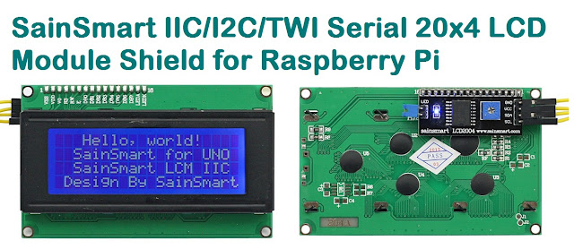
Hitachi HD44780 based 16x2 character LCD are very cheap and widely available, and is a essential part for any projects that displays information. Using the I2C bus on Raspberry Pi ,PCF8574 IC, and Python characters/strings can be displayed on the LCD. The PCF8574 is an general purpose bidirectional 8 bit I/O port expander that uses the I2C protocol.
The LCD(HD44780) is connected in 4 bit mode as follows to the PCF8574:-

P0 - D4
P1 - D5
P2 - D6
P3 - D7
P4 - RS
P5 - R/W
P6 - E
Port A0 is connected to VCC(5V) with a 10k resistor so that it will be addressed at 0x21.


import smbus
from time import *
# General i2c device class so that other devices can be added easily
class i2c_device:
 def __init__(self, addr, port):
  self.addr = addr
  self.bus = smbus.SMBus(port)
 def write(self, byte):
  self.bus.write_byte(self.addr, byte)
 def read(self):
  return self.bus.read_byte(self.addr)
 def read_nbytes_data(self, data, n): # For sequential reads > 1 byte
  return self.bus.read_i2c_block_data(self.addr, data, n)
class lcd:
 #initializes objects and lcd
 '''
 Reverse Codes:
 0: lower 4 bits of expander are commands bits
 1: top 4 bits of expander are commands bits AND P0-4 P1-5 P2-6
 2: top 4 bits of expander are commands bits AND P0-6 P1-5 P2-4
 '''
 def __init__(self, addr, port, reverse=0):
  self.reverse = reverse
  self.lcd_device = i2c_device(addr, port)
  if self.reverse:
   self.lcd_device.write(0x30)
   self.lcd_strobe()
   sleep(0.0005)
   self.lcd_strobe()
   sleep(0.0005)
   self.lcd_strobe()
   sleep(0.0005)
   self.lcd_device.write(0x20)
   self.lcd_strobe()
   sleep(0.0005)
  else:
   self.lcd_device.write(0x03)
   self.lcd_strobe()
   sleep(0.0005)
   self.lcd_strobe()
   sleep(0.0005)
   self.lcd_strobe()
   sleep(0.0005)
   self.lcd_device.write(0x02)
   self.lcd_strobe()
   sleep(0.0005)
  self.lcd_write(0x28)
  self.lcd_write(0x08)
  self.lcd_write(0x01)
  self.lcd_write(0x06)
  self.lcd_write(0x0C)
  self.lcd_write(0x0F)
 # clocks EN to latch command
 def lcd_strobe(self):
  if self.reverse == 1:
   self.lcd_device.write((self.lcd_device.read() | 0x04))
   self.lcd_device.write((self.lcd_device.read() & 0xFB))
  if self.reverse == 2:
   self.lcd_device.write((self.lcd_device.read() | 0x01))
   self.lcd_device.write((self.lcd_device.read() & 0xFE))
  else:
   self.lcd_device.write((self.lcd_device.read() | 0x10))
   self.lcd_device.write((self.lcd_device.read() & 0xEF))
 # write a command to lcd
 def lcd_write(self, cmd):
  if self.reverse:
   self.lcd_device.write((cmd >> 4)<<4 0x0f="" cmd="" else:="" self.lcd_device.write="" self.lcd_strobe="" x0="">> 4))
   self.lcd_strobe()
   self.lcd_device.write((cmd & 0x0F))
   self.lcd_strobe()
   self.lcd_device.write(0x0)
 # write a character to lcd (or character rom)
 def lcd_write_char(self, charvalue):
  if self.reverse == 1:
   self.lcd_device.write((0x01 | (charvalue >> 4)<<4 0x0f="" 2:="" charvalue="" if="" self.lcd_device.write="" self.lcd_strobe="" self.reverse="=" x01="" x04="" x0="">> 4)<<4 0x0f="" charvalue="" else:="" self.lcd_device.write="" self.lcd_strobe="" x04="" x0="" x40="">> 4)))
   self.lcd_strobe()
   self.lcd_device.write((0x40 | (charvalue & 0x0F)))
   self.lcd_strobe()
   self.lcd_device.write(0x0)
 # put char function
 def lcd_putc(self, char):
  self.lcd_write_char(ord(char))
 # put string function
 def lcd_puts(self, string, line):
  if line == 1:
   self.lcd_write(0x80)
  if line == 2:
   self.lcd_write(0xC0)
  if line == 3:
   self.lcd_write(0x94)
  if line == 4:
   self.lcd_write(0xD4)
  for char in string:
   self.lcd_putc(char)
 # clear lcd and set to home
 def lcd_clear(self):
  self.lcd_write(0x1)
  self.lcd_write(0x2)
 # add custom characters (0 - 7)
 def lcd_load_custon_chars(self, fontdata):
  self.lcd_device.bus.write(0x40);
  for char in fontdata:
   for line in char:
    self.lcd_write_char(line)
Main Program:-
import pylcdlib
lcd = pylcdlib.lcd(0x21,0)
lcd.lcd_puts("Raspberry Pi",1)  #display "Raspberry Pi" on line 1
lcd.lcd_puts("  Take a byte!",2)  #display "Take a byte!" on line 2
Save the above code as test_lcd.py and enter sudo python test_lcd.py
My code assumes that the first 4 bits of the LCD(11,12,13,14) are connected to P0,P1,P2,P3 ports on PCF8574. The next 3 ports on PCF8574(P4,P5,P6) should be connected to 4-RS, 5-R/W, 6-E.However there are other serial backpack lcd's with different pinouts. According to the wiring of your serial backpack LCD you can override the default mapping during initialization.There are 3 modes available-
lcd = pylcdlib.lcd(0x21,0) lower 4 bits of expander are commands bits
lcd = pylcdlib.lcd(0x21,0,1) top 4 bits of expander are commands bits AND P0-4 P1-5 P2-6
lcd = pylcdlib.lcd(0x21,0,2) top 4 bits of expander are commands bits AND P0-6 P1-5 P2-4
(Update):- If you have a Raspberry Pi with a revision 2.0 board, you need to use I²C bus 1, not bus 0, so you will need to change the bus number used. In this case, the line lcd = pylcdlib.lcd(0x21,0) would become lcd = pylcdlib.lcd(0x21,1).
You can check that the device is present on the bus by using the i2cdetect program from the i2ctools package-
i2cdetect 0 -y or i2cdetect 1 -y
Compatible LCD Module for this article:-