The prototype tablet can run Android 4.4 or Debian. However, any Linux distribution that is compatible with the motherboard of Raspberry Pi or ODROID can be installed.


Compatibility with Arduino is also planned for future releases.
For home automation users, a wall bracket and POE + power is also included for easy integration,
As of now, the project is not yet funded, but many indicators show that the demand is there, especially in the community of free home automation sector.
The project leader, Guillaume, is looking forward to your feedback survey, which is currently available at: http://goo.gl/forms/6GvKsm5OtL
Once a second prototype is ready, participatory financing (crowdfunding) will be implemented during 2016.
For details visit: www.diskiopi.com

RAIO is a panel PC with touch screen based on Raspberry Pi. It is a simple solution for everyone who wants to use Pi platform. We decided to make durable plastic case for 15" LCD screen size to create a complex station for open source desingers
The project is intended to facilitate the use of Raspberry Pi. The users get a computer with Raspberry heart ready for playing.
3D Model from sketchfab:
Raio Raspberry All-In-One Pc With 15" Touch Lcd
by roxor1992
on Sketchfab
- Computer home users
- Electronics hobbyist
- Programming students
- Young developers
- Programming and electronics school teachers
- Teaching organizations
For more information visit their indiegogo campaign: https://www.indiegogo.com/projects/raspberry-all-in-one-pc-with-15-touch-lcd-screen
In my previous post I had used an 8 bit i2c port expander to drive the 16x2 LCD. It saved precious GPIO pins but added complexity and cost. In this post I will be using the RPi.GPIO library and Python to control the LCD.The LCD used in this post is based on Hitachi HD44780 LCD controller.Although the LCD has 16 pins available for interfacing, using the 4 bit mode only 6 GPIO pins are required ( RS,E,D4,D5,D6,D7).

LCD Pin Pi Pin
01 <------> GPIO-06
02 <------> GPIO-02
03 <------> GPIO-06
04 <------> GPIO-26
05 <------> GPIO-06
06 <------> GPIO-24
07
08
09
10
11 <------> GPIO-22
12 <------> GPIO-18
13 <------> GPIO-16
14 <------> GPIO-12
15 +5V
16 <------> GPIO-06
NOTE : With the help of RW pin the device can be set to read/write mode.Setting [R/W=0] will write to the register and setting [R/W=1] will read from the register.To display data on LCD read access is not required,so the RW in connected to GND. This ensures that there is no outbound data from HD44780 as Pi cannot tolerate 5V.
You can check the pinout of Pi from here.
Code:-
HD44780 based display can be controlled using any programming environment.Here I have used Python & RPi.GPIO library to provide access to the GPIO.

LCD Pin Pi Pin
01 <------> GPIO-06
02 <------> GPIO-02
03 <------> GPIO-06
04 <------> GPIO-26
05 <------> GPIO-06
06 <------> GPIO-24
07
08
09
10
11 <------> GPIO-22
12 <------> GPIO-18
13 <------> GPIO-16
14 <------> GPIO-12
15 +5V
16 <------> GPIO-06
You can check the pinout of Pi from here.
Code:-
HD44780 based display can be controlled using any programming environment.Here I have used Python & RPi.GPIO library to provide access to the GPIO.
#!/usr/bin/python
import RPi.GPIO as GPIO
from time import sleep
class HD44780:
    def __init__(self, pin_rs=7, pin_e=8, pins_db=[25, 24, 23, 18]):
        self.pin_rs=pin_rs
        self.pin_e=pin_e
        self.pins_db=pins_db
        GPIO.setmode(GPIO.BCM)
        GPIO.setup(self.pin_e, GPIO.OUT)
        GPIO.setup(self.pin_rs, GPIO.OUT)
        for pin in self.pins_db:
            GPIO.setup(pin, GPIO.OUT)
        self.clear()
    def clear(self):
        """ Blank / Reset LCD """
        self.cmd(0x33) # $33 8-bit mode
        self.cmd(0x32) # $32 8-bit mode
        self.cmd(0x28) # $28 8-bit mode
        self.cmd(0x0C) # $0C 8-bit mode
        self.cmd(0x06) # $06 8-bit mode
        self.cmd(0x01) # $01 8-bit mode
    def cmd(self, bits, char_mode=False):
        """ Send command to LCD """
        sleep(0.001)
        bits=bin(bits)[2:].zfill(8)
        GPIO.output(self.pin_rs, char_mode)
        for pin in self.pins_db:
            GPIO.output(pin, False)
        for i in range(4):
            if bits[i] == "1":
                GPIO.output(self.pins_db[::-1][i], True)
        GPIO.output(self.pin_e, True)
        GPIO.output(self.pin_e, False)
        for pin in self.pins_db:
            GPIO.output(pin, False)
        for i in range(4,8):
            if bits[i] == "1":
                GPIO.output(self.pins_db[::-1][i-4], True)
        GPIO.output(self.pin_e, True)
        GPIO.output(self.pin_e, False)
    def message(self, text):
        """ Send string to LCD. Newline wraps to second line"""
        for char in text:
            if char == '\n':
                self.cmd(0xC0) # next line
            else:
                self.cmd(ord(char),True)
if __name__ == '__main__':
    lcd = HD44780()
    lcd.message("Raspberry Pi\n  Take a byte!")


Hitachi HD44780 based 16x2 character LCD are very cheap and widely available, and is a essential part for any projects that displays information. Using the I2C bus on Raspberry Pi ,PCF8574 IC, and Python characters/strings can be displayed on the LCD. The PCF8574 is an general purpose bidirectional 8 bit I/O port expander that uses the I2C protocol.
The LCD(HD44780) is connected in 4 bit mode as follows to the PCF8574:-

P0 - D4
P1 - D5
P2 - D6
P3 - D7
P4 - RS
P5 - R/W
P6 - E
Port A0 is connected to VCC(5V) with a 10k resistor so that it will be addressed at 0x21.


import smbus
from time import *
# General i2c device class so that other devices can be added easily
class i2c_device:
 def __init__(self, addr, port):
  self.addr = addr
  self.bus = smbus.SMBus(port)
 def write(self, byte):
  self.bus.write_byte(self.addr, byte)
 def read(self):
  return self.bus.read_byte(self.addr)
 def read_nbytes_data(self, data, n): # For sequential reads > 1 byte
  return self.bus.read_i2c_block_data(self.addr, data, n)
class lcd:
 #initializes objects and lcd
 '''
 Reverse Codes:
 0: lower 4 bits of expander are commands bits
 1: top 4 bits of expander are commands bits AND P0-4 P1-5 P2-6
 2: top 4 bits of expander are commands bits AND P0-6 P1-5 P2-4
 '''
 def __init__(self, addr, port, reverse=0):
  self.reverse = reverse
  self.lcd_device = i2c_device(addr, port)
  if self.reverse:
   self.lcd_device.write(0x30)
   self.lcd_strobe()
   sleep(0.0005)
   self.lcd_strobe()
   sleep(0.0005)
   self.lcd_strobe()
   sleep(0.0005)
   self.lcd_device.write(0x20)
   self.lcd_strobe()
   sleep(0.0005)
  else:
   self.lcd_device.write(0x03)
   self.lcd_strobe()
   sleep(0.0005)
   self.lcd_strobe()
   sleep(0.0005)
   self.lcd_strobe()
   sleep(0.0005)
   self.lcd_device.write(0x02)
   self.lcd_strobe()
   sleep(0.0005)
  self.lcd_write(0x28)
  self.lcd_write(0x08)
  self.lcd_write(0x01)
  self.lcd_write(0x06)
  self.lcd_write(0x0C)
  self.lcd_write(0x0F)
 # clocks EN to latch command
 def lcd_strobe(self):
  if self.reverse == 1:
   self.lcd_device.write((self.lcd_device.read() | 0x04))
   self.lcd_device.write((self.lcd_device.read() & 0xFB))
  if self.reverse == 2:
   self.lcd_device.write((self.lcd_device.read() | 0x01))
   self.lcd_device.write((self.lcd_device.read() & 0xFE))
  else:
   self.lcd_device.write((self.lcd_device.read() | 0x10))
   self.lcd_device.write((self.lcd_device.read() & 0xEF))
 # write a command to lcd
 def lcd_write(self, cmd):
  if self.reverse:
   self.lcd_device.write((cmd >> 4)<<4 0x0f="" cmd="" else:="" self.lcd_device.write="" self.lcd_strobe="" x0="">> 4))
   self.lcd_strobe()
   self.lcd_device.write((cmd & 0x0F))
   self.lcd_strobe()
   self.lcd_device.write(0x0)
 # write a character to lcd (or character rom)
 def lcd_write_char(self, charvalue):
  if self.reverse == 1:
   self.lcd_device.write((0x01 | (charvalue >> 4)<<4 0x0f="" 2:="" charvalue="" if="" self.lcd_device.write="" self.lcd_strobe="" self.reverse="=" x01="" x04="" x0="">> 4)<<4 0x0f="" charvalue="" else:="" self.lcd_device.write="" self.lcd_strobe="" x04="" x0="" x40="">> 4)))
   self.lcd_strobe()
   self.lcd_device.write((0x40 | (charvalue & 0x0F)))
   self.lcd_strobe()
   self.lcd_device.write(0x0)
 # put char function
 def lcd_putc(self, char):
  self.lcd_write_char(ord(char))
 # put string function
 def lcd_puts(self, string, line):
  if line == 1:
   self.lcd_write(0x80)
  if line == 2:
   self.lcd_write(0xC0)
  if line == 3:
   self.lcd_write(0x94)
  if line == 4:
   self.lcd_write(0xD4)
  for char in string:
   self.lcd_putc(char)
 # clear lcd and set to home
 def lcd_clear(self):
  self.lcd_write(0x1)
  self.lcd_write(0x2)
 # add custom characters (0 - 7)
 def lcd_load_custon_chars(self, fontdata):
  self.lcd_device.bus.write(0x40);
  for char in fontdata:
   for line in char:
    self.lcd_write_char(line)
Main Program:-
import pylcdlib
lcd = pylcdlib.lcd(0x21,0)
lcd.lcd_puts("Raspberry Pi",1)  #display "Raspberry Pi" on line 1
lcd.lcd_puts("  Take a byte!",2)  #display "Take a byte!" on line 2
Save the above code as test_lcd.py and enter sudo python test_lcd.py
My code assumes that the first 4 bits of the LCD(11,12,13,14) are connected to P0,P1,P2,P3 ports on PCF8574. The next 3 ports on PCF8574(P4,P5,P6) should be connected to 4-RS, 5-R/W, 6-E.However there are other serial backpack lcd's with different pinouts. According to the wiring of your serial backpack LCD you can override the default mapping during initialization.There are 3 modes available-
lcd = pylcdlib.lcd(0x21,0) lower 4 bits of expander are commands bits
lcd = pylcdlib.lcd(0x21,0,1) top 4 bits of expander are commands bits AND P0-4 P1-5 P2-6
lcd = pylcdlib.lcd(0x21,0,2) top 4 bits of expander are commands bits AND P0-6 P1-5 P2-4
(Update):- If you have a Raspberry Pi with a revision 2.0 board, you need to use I²C bus 1, not bus 0, so you will need to change the bus number used. In this case, the line lcd = pylcdlib.lcd(0x21,0) would become lcd = pylcdlib.lcd(0x21,1).
You can check that the device is present on the bus by using the i2cdetect program from the i2ctools package-
i2cdetect 0 -y or i2cdetect 1 -y
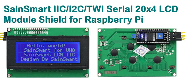
Compatible LCD Module for this article:-