Hitachi HD44780 based 16x2 character LCD are very cheap and widely available, and is a essential part for any projects that displays information. Using the I2C bus on Raspberry Pi ,PCF8574 IC, and Python characters/strings can be displayed on the LCD. The PCF8574 is an general purpose bidirectional 8 bit I/O port expander that uses the I2C protocol.
The LCD(HD44780) is connected in 4 bit mode as follows to the PCF8574:-

P0 - D4
P1 - D5
P2 - D6
P3 - D7
P4 - RS
P5 - R/W
P6 - E
Port A0 is connected to VCC(5V) with a 10k resistor so that it will be addressed at 0x21.


import smbus
from time import *
# General i2c device class so that other devices can be added easily
class i2c_device:
 def __init__(self, addr, port):
  self.addr = addr
  self.bus = smbus.SMBus(port)
 def write(self, byte):
  self.bus.write_byte(self.addr, byte)
 def read(self):
  return self.bus.read_byte(self.addr)
 def read_nbytes_data(self, data, n): # For sequential reads > 1 byte
  return self.bus.read_i2c_block_data(self.addr, data, n)
class lcd:
 #initializes objects and lcd
 '''
 Reverse Codes:
 0: lower 4 bits of expander are commands bits
 1: top 4 bits of expander are commands bits AND P0-4 P1-5 P2-6
 2: top 4 bits of expander are commands bits AND P0-6 P1-5 P2-4
 '''
 def __init__(self, addr, port, reverse=0):
  self.reverse = reverse
  self.lcd_device = i2c_device(addr, port)
  if self.reverse:
   self.lcd_device.write(0x30)
   self.lcd_strobe()
   sleep(0.0005)
   self.lcd_strobe()
   sleep(0.0005)
   self.lcd_strobe()
   sleep(0.0005)
   self.lcd_device.write(0x20)
   self.lcd_strobe()
   sleep(0.0005)
  else:
   self.lcd_device.write(0x03)
   self.lcd_strobe()
   sleep(0.0005)
   self.lcd_strobe()
   sleep(0.0005)
   self.lcd_strobe()
   sleep(0.0005)
   self.lcd_device.write(0x02)
   self.lcd_strobe()
   sleep(0.0005)
  self.lcd_write(0x28)
  self.lcd_write(0x08)
  self.lcd_write(0x01)
  self.lcd_write(0x06)
  self.lcd_write(0x0C)
  self.lcd_write(0x0F)
 # clocks EN to latch command
 def lcd_strobe(self):
  if self.reverse == 1:
   self.lcd_device.write((self.lcd_device.read() | 0x04))
   self.lcd_device.write((self.lcd_device.read() & 0xFB))
  if self.reverse == 2:
   self.lcd_device.write((self.lcd_device.read() | 0x01))
   self.lcd_device.write((self.lcd_device.read() & 0xFE))
  else:
   self.lcd_device.write((self.lcd_device.read() | 0x10))
   self.lcd_device.write((self.lcd_device.read() & 0xEF))
 # write a command to lcd
 def lcd_write(self, cmd):
  if self.reverse:
   self.lcd_device.write((cmd >> 4)<<4 0x0f="" cmd="" else:="" self.lcd_device.write="" self.lcd_strobe="" x0="">> 4))
   self.lcd_strobe()
   self.lcd_device.write((cmd & 0x0F))
   self.lcd_strobe()
   self.lcd_device.write(0x0)
 # write a character to lcd (or character rom)
 def lcd_write_char(self, charvalue):
  if self.reverse == 1:
   self.lcd_device.write((0x01 | (charvalue >> 4)<<4 0x0f="" 2:="" charvalue="" if="" self.lcd_device.write="" self.lcd_strobe="" self.reverse="=" x01="" x04="" x0="">> 4)<<4 0x0f="" charvalue="" else:="" self.lcd_device.write="" self.lcd_strobe="" x04="" x0="" x40="">> 4)))
   self.lcd_strobe()
   self.lcd_device.write((0x40 | (charvalue & 0x0F)))
   self.lcd_strobe()
   self.lcd_device.write(0x0)
 # put char function
 def lcd_putc(self, char):
  self.lcd_write_char(ord(char))
 # put string function
 def lcd_puts(self, string, line):
  if line == 1:
   self.lcd_write(0x80)
  if line == 2:
   self.lcd_write(0xC0)
  if line == 3:
   self.lcd_write(0x94)
  if line == 4:
   self.lcd_write(0xD4)
  for char in string:
   self.lcd_putc(char)
 # clear lcd and set to home
 def lcd_clear(self):
  self.lcd_write(0x1)
  self.lcd_write(0x2)
 # add custom characters (0 - 7)
 def lcd_load_custon_chars(self, fontdata):
  self.lcd_device.bus.write(0x40);
  for char in fontdata:
   for line in char:
    self.lcd_write_char(line)
Main Program:-
import pylcdlib
lcd = pylcdlib.lcd(0x21,0)
lcd.lcd_puts("Raspberry Pi",1)  #display "Raspberry Pi" on line 1
lcd.lcd_puts("  Take a byte!",2)  #display "Take a byte!" on line 2
Save the above code as test_lcd.py and enter sudo python test_lcd.py
My code assumes that the first 4 bits of the LCD(11,12,13,14) are connected to P0,P1,P2,P3 ports on PCF8574. The next 3 ports on PCF8574(P4,P5,P6) should be connected to 4-RS, 5-R/W, 6-E.However there are other serial backpack lcd's with different pinouts. According to the wiring of your serial backpack LCD you can override the default mapping during initialization.There are 3 modes available-
lcd = pylcdlib.lcd(0x21,0) lower 4 bits of expander are commands bits
lcd = pylcdlib.lcd(0x21,0,1) top 4 bits of expander are commands bits AND P0-4 P1-5 P2-6
lcd = pylcdlib.lcd(0x21,0,2) top 4 bits of expander are commands bits AND P0-6 P1-5 P2-4
(Update):- If you have a Raspberry Pi with a revision 2.0 board, you need to use I²C bus 1, not bus 0, so you will need to change the bus number used. In this case, the line lcd = pylcdlib.lcd(0x21,0) would become lcd = pylcdlib.lcd(0x21,1).
You can check that the device is present on the bus by using the i2cdetect program from the i2ctools package-
i2cdetect 0 -y or i2cdetect 1 -y
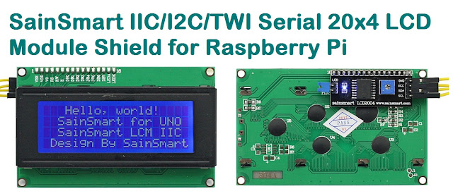
Compatible LCD Module for this article:-