
Interface
User Interface
User interface is the primary interface for end users. That is where the smart home owner gets and applies the effective management and control tools. intraHouse's user interface is designed to work on a great variety of devices and is accessible from a Web-browser. It means that you won’t need to install any software on your personal computer, tablet or smart phone. It also means that the user interface will be compatible with any operational system (Android, iOS , Linux, Mac OS X, Windows). It is designed keeping simplicity in mind and it's very user friendly. The system interface supports multiple access simultaneously and synchronizes across all devices in real time.
 |
| User Interface |
Installer Interface
Installer interface is intended for project and building managers and focuses mainly on system setup and settings. This panel consists of all the system settings and customization panes. It's fully customizable interface allows to perfectly fit control panels in the interior design, adjust the menu look, change pictographs etc. Any changes that are made in Project Manager will be saved on the server and become immediately accessible for all system users. Users can also apply various themes that comes along with it and customize it accordingly.
 |
| Installer Interface |
In the basic version of intraHouse system, three standard modes are available: Day, Night and Economy.
Normally those three modes, together with scenes, are enough to provide fully-featured energy efficient and comfortable management of a flat or a house.
You can adjust those three modes for other purposes. For example, you can have such modes as “Business Hours”, “Off Hours”, “Holidays”. For you summer house, you can have “Home”, “Away”, “In Conservation”.
Scenes
What is a scene? In a typical Smart Home system, a scene normally means a lighting scene.
In intraHouse system, the concept of Scene has a broader meaning: it means management of all devices in accordance with particular algorithms.
All devices in intraHouse system can operate without scenes: you can turn them on/off and watch the change in their condition.
System Structure
Functionally, intraHouse system comprises three main components: intraHouse.Server, intraHouse.Plugins and intraHouse.Apps

intraHouse.Server
It includes Kernel (the system’s core), Script Engine, Front Server (Web server), Back Server (communication with devices). intraHouse Server is based on Node.js platform.
intraHouse.Apps
intraHouse.Apps are front-end web applications that ensure visualization. These applications work on any devices with a web-browser: i.e., smart phones, tablets and computers. Modern TV sets also work with intraHouse system. They are implemented using HTML5, CSS3, jQuery, Socket.io and other technologies.
intraHouse.Plugins
Plugins are intended for connection of equipment of different manufacturers. They are drivers that link shortcuts in the interface with actual devices.
Live Demo
If you are interested in intraHouse's home automation package, you can check out the live demo of the interface here.

Since PiCapture fully emulates the Raspberry Pi camera module, all software such as Raspivid, PiCamera and related applications are fully compatible. The robust design and rugged mechanical package makes PiCapture suitable for a wide range of applications including crucial ones for medical and industrial use.
PiCapture comes in two variants:

interlaced video (NTSC/PAL) from Composite,
S-Video, and YPbPr Component
- PiCapture HD1 for high-definition progressive
video from digital (HDMI/DVI), analog (YPbPr
Component), and Computer (RGB) sources at
480p, 720p, and 1080p resolutions
Features at a Glance:
● Form Factor: Raspberry Pi HAT compatible.
● High Speed Interface: Raspberry Pi Camera port - MIPI CSI-2.
● Assured Compatibility: Works with most Raspberry Pi boards (including 3.0) and standard camera software (raspivid, picamera, etc.)
● FULLY EMULATES THE RASPBERRY PI CAMERA: MIPI CSI-2 interface means the Raspberry Pi GPU can be used to its fullest and the CPU is free for you own applications not
consumed with peripherals.
● PIVIDEO PYTHON-BASED CONTROL SOFTWARE: PiVideo is used to control the PiCapture processor for:
- Automatic or manual video source selection
- Optional on-screen source indication
- Test mode control - B&W modes, solid color, and color pattern
- Firmware update utility
● MULTIPLE WAYS TO COMMUNICATE WITH RASPBERRY PI: Jumpers for selecting UART, I2C1, I2C0 (or none) for maximum flexibility of Raspberry Pi GPIO
● GET UP AND RUNNING FAST WITH ANY VIDEO SOURCE: PiCapture products are fully compatible with Raspberry Pi hardware and software so no special drivers required. Connect, power up, and run raspivid or your software, and capture video for any SD or HD source!
Application Areas:
● Video streaming
● Video recording
● Machine vision
● Manufacturing
● Robotics
● Security and Surveillance
● Baby/child/pet monitors
● Healthcare (telemedicine)
● Traffic monitoring
● Astronomy/Astrophotography
● DVR/Media Center
…. and more
To learn more about PiCapture do visit their site: www.lintestsystems.com. Be sure to check out the sample videos captured with PiCapture here.
To learn more about PiCapture do visit their site: www.lintestsystems.com. Be sure to check out the sample videos captured with PiCapture here.

What Can You Make With the Pi Platter?
The Pi Platter is a very versatile board. For starters, you can use it to make:
- Robots
- Remote server
- Solar power management
- Mini Tablets
- Wildlife Cameras
- Hydroponics and greenhouse controllers
- Various remote Internet of Things applications
- And much more
 |
| Pi Platter: A world of expansion without using a single GPIO pin |
Features of the Solar Pi Platter include :
- Smart UPS (Uninterruptible Power Supply) allows you to power your project directly from an attached USB charger and automatically switch over to the battery if the power fails. The Pi Platter makes sure the battery is charged and warns the Pi of low battery so it can shutdown properly.
- Optimized Solar Charger so you can power your Pi from the Sun for remote applications. Special features allow you to shutdown the Pi when the power is low and the automatically restart the Pi again when the battery is charged.
- Supports a wide range of LiPo batteries to match your specific needs.
- Real Time Clock with repeating alarm keeps track of time when the Pi is off and schedule times to start the Pi (great for remote time lapse photography).
- Header that matches a Sparkfun break-out board for adding a direct Ethernet port.
- 3 High Speed USB ports with multiple queues allow different speed devices to operate simultaneously. Much faster than other Pi Zero USB boards that force all USB devices to operate as fast as the slowest device. Two of the USB ports are power-switched so you can optimize power consumption in your application.
- Low Power micro controller interfaces your application to the Pi Platter through a simple USB serial port so it does not tie up any GPIO pins. You still have all the GPIO pins available.
- 2 x 10 bit Analog Inputs let you interface to the real world.
- 2 x 8 PWM Outputs, that can also be configured to drive standard RC servo motors, let you control motors, LEDs and real world devices.
- Store board configuration even when power is off to let you power up without error.
To learn more about the Solar/UPS Pi Platter for Raspberry Pi do visit their KickStarter Page and make a pledge if you are interested. More technical details regarding this project can be found at: https://hackaday.io/project/9819-solar-pi-platter.

GrovePi-Zero lets you use various sensors in the Grove family to enhance your projects: everything from a distance sensor, light sensor, temperature and humidity sensor, buttons, and displays. There are literally hundreds of Grove Sensors and I/O modules available for your project!

The GrovePi Zero comes with many options for programming. You can program for it in Python, C, Java, and Scratch. Apart from that you can also leverage their open source programming examples and libraries which makes it easier to connect Grove sensors and interact with the physical world.
To learn more about the new GrovePi-Zero do visit their Kickstarter page and make a pledge if you are interested.

For all you audio lovers out there, Flatmax Studios have come up with a decent quality Audio Injector Sound Card for the Raspberry Pi that uses both DAC and ADC for audio out and or in. It’s a cost effective solution for projects that needs decent audio capabilities. There are so many different projects which you can create using this sound card - audio to and from almost any of the devices on the Raspberry Pi, such as disk, USB, HDMI, WiFi, the Ethernet network and so on.
The Raspberry Pi Audio Injector Sound Card provides 2 channels of audio input and 2 channels of audio output. It comes equipped with volume knobs for controlling both inputs and outputs. Apart from these, it also includes a headphone preamp+jack and an inbuilt electret microphone. The headphone jack is expected to deliver 50 mW max power into 16 Ohm and 30 mW max power into 32 Ohm headphones.
This sound-card boasts low jitter operation using a crystal driven codec as the timing master. It also allows you to stack more Raspberry Pi HATS on top if required.
Specifications:
· Microphone: Inbuilt electret microphone with mixer controls. Allowing voice control or other applications.
· Headphones: 50 mW max power into 16 ohm and 30 mW max power into 32 Ohm headphones (check the updates to see more)
· Driver : ALSA
· Linux : Already integrated into the Raspberry Pi kernel. If you have an older version of the kernel, simply run "rpi-update" if you need to. Edit /boot/config.txt and set dtoverlay=audioinjector-soundcard
· DAC and ADC : 96 kHz, 32 bit audio.
· GPIO : Standard 40 Pin header, broken out above the add on card to accept more add on cards and hats.
To learn more about the new Raspberry Pi Audio Injector Sound Card do visit their Kickstarter page and make a pledge if you are interested.
Source: Kickstarter

By using the Raspberry Pi Compute Module, the platform is fully compatible with existing Raspberry Pi ecosystem. This in turn will allow you to leverage the seemingly endless libraries of code, application notes and peripherals that are already available.
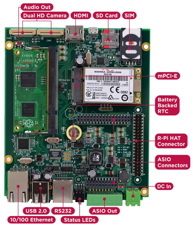
Product Features:
· Integrated 10/100 Ethernet Adapter
· Dual High-Resolution Raspberry Pi Camera Interfaces
· Mini PCI-E Interface + SIM connector
· High Speed SD compliant Micro SD Card interface
· ASIO Connectors allowing more comprehensive Application Specific solutions
· Raspberry Pi 2 HAT Compatible I/O Connector & Mounting Points (4 x M2.5)
· Independent USB UART (RX/TX/RTS/CTS)
· HDMI Out
· 8Way 2 part 3.5mm Phoenix industrial connector for use with ASIO Outputs or HAT board
· Integrated battery backed Real-Time-Clock (RTC)
· 2 x Bi-Colour (Red/Green) front panel status LEDs
· Wide 7-23V (poly-fused and filtered) High capacity DC power input via either 2 part Phoenix screw terminal front panel connector or internal 2way Molex AM254 Connector
HAT Compatible
Because the platform uses a standard HAT connector it's also backwards compatible with RPi HAT boards that you may already have or want to use, even allowing you to bring HAT IO connectivity out of the front using the industrial connector.
I/O Cards
In order to retain flexibility for various different IO configurations they have opted to use I/O connector in, instead of the actual I/O. So instead of plugging in HAT card with I/O signal connectors poking out on all sides, they have these same I/O signals back down a second output connector which is directly connected to the green industrial connector.
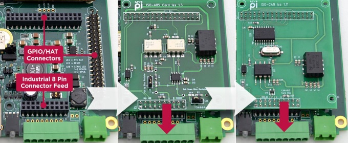
The added bonus here is that by simply using extended length interface pins on the card (raising it up) you can expand the IO set further - all without using any cable assemblies! They have pre-designed a series of hardened plug in cards for dealing common applications like CAN-Bus, 4-20mA transducer signals, RS485, Narrow Band RF and others. This way you have to spend less time dealing with hardware and more time focusing on software development.
Enclosure Design
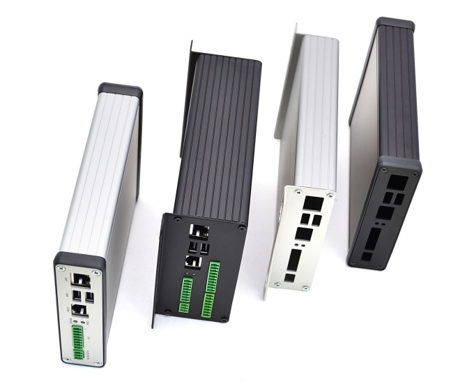
The best thing about their enclosure type is that they require only the end plates to be punched to match the board connectors, which reduces the design and manufacturing costs involved significantly. The PCB features 4 mounting holes, making it easy to install inside a larger or custom enclosure design if required.
The enclosure comes in two sizes, a low profile version and a larger double height model allowing extra room. All the single function I/O cards designed have been built with the lowest profile enclosure type in mind allowing for a neat solution.
Head over to Kickstarter to read more or to back the campaign.
Head over to Kickstarter to read more or to back the campaign.

Although its very simple but you still need to configure 2 files (config.txt & cmdline.txt). Editing the files can be done on Windows as the configuration files are located on the /boot partition, which is formatted FAT32 and readable on Windows/Mac/Linux.
Prerequisites:
1. 2016-05-10 release of Raspbian
2. SD Card
3. Standard Micro USB Cable
4. Windows: iTunes installed, Linux: Avahi Daemon installed
Setup:
Step 1: Step 1 is pretty obvious. You need to flash Raspbian onto the SD card. You can use win32diskimager for this.
Step 2: After flashing is complete, navigate to the boot partition. Open "config.txt" file and add "dtoverlay=dwc2" at the bottom of the file on a new line. Save the file and close it.

Step 3: Next open "cmdline.txt" file and add "modules-load=dwc2,g_ether" after rootwait. Make sure that there is a single space gap in between the parameters. Do not alter the format! . Save the file and close it.

Step 4: Boot your Pi Zero using the configured SD card. The first time you boot your Pi Zero connected to your your Windows machine, one of two things will happen. You'll either see a new RNDIS network device, or you won't. If the drivers are not installed it's will not work and will show a yellow exclamation mark on top of "USB Ethernet/RNDIS Gadget".

If you are on Windows 10 right-click on it and select "Update Driver Software"..., then "Browse my computer for driver software" and then "Let me pick from a list of device drivers on my computer" and finally choose "Remote NDIS Compatible Device". This should install the Microsoft RNDIS 5.1 driver (shows "Acer" as the manufacturer).

Step 5: If you have Bonjour Service running you should be able to SSH into you Pi Zero using raspberrypi.local as the address.

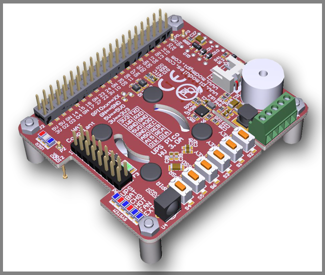
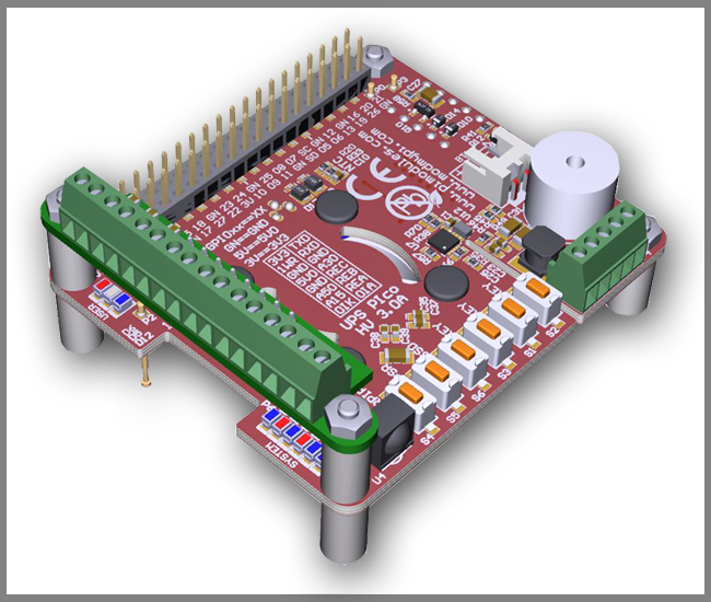
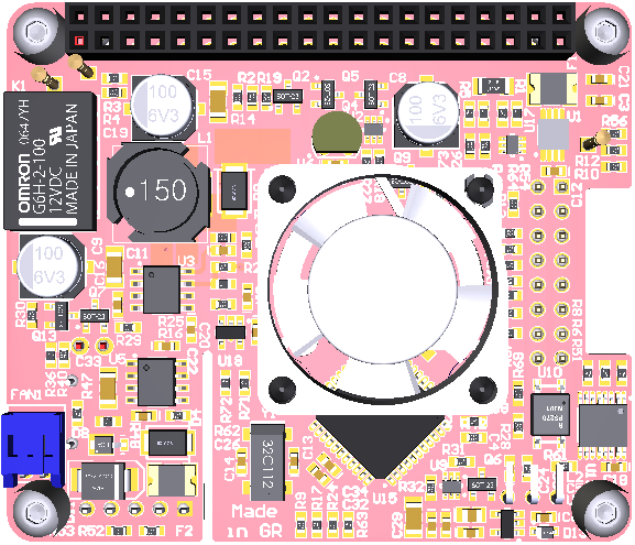
It is specially designed for the Raspberry Pi® 3 but it's also compatible with all other models. It comes equipped with 3 User Keys, 3 User LEDs, 3 different types of high capacity batteries, 2 x 3 pins bi-stable relay (Zero Power), as also 3 x A/D 12 bit converters pre-adjusted to 5V, 15V and 30V conversion.
Power Specifications:
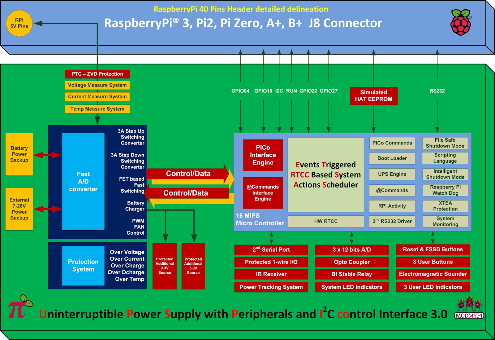
Pimodules have implemented a Dynamic Power Tracking feature that can automatically adjust battery charging current according to power availability ranging from 50mA - 1000 mAh. This feature has been especially designed to support Solar Panel Powering Raspberry Pi® Systems, as the output from solar panel can vary according to weather conditions. UPS PIco HV3.0A can accept external voltage input ranging from 7 V DC up to 28 V DC !! This makes it ideal for use in Cars, Trucks, Buses and any industrial applications where voltage is usually higher than 24V DC. The External Supply Powering Input is equipped with Over Current protection, Over Voltage as also with Zero Voltage Drop Inverse Polarity Protection in order to use all available energy from the solar panel.
Product Overview:
The UPS PIco HV3.0A is equipped with a standard 450 mAh 15C LiPO battery specially designed to enable safe shutdown during mains power failure. The included battery provides enough power to keep running the system for 5-8 minutes. Additionally, you can also upgrade the battery capacity to 4000mAh, 8000 mAh or 12000 mAh batteries (optional on special request). With 12000 mAh batteries on board, you can use your Raspberry Pi for more than 32 hours without a power supply connected!
The UPS PIco HV3.0A 450 mAh Stack Plus design supports 2 types of lithium cell chemistry: LiPO as also LiFePO4. LiFePO4 batteries are useful in applications where temperature environment is more restricted which can range from -10 degrees up to +60 degrees. In addition, the LiFePO4 chemistry offers a longer cycle life than other lithium-ion cells out there. It can achieve up to 2000 cycles!!
Peripherals
1. RTCC: UPS PIco HV3.0A comes with a integrated Hardware Real Time Clock and Calendar, which keeps time even when the system is running without access to the Network. The Hardware RTCC is backed up and powered from the integrated system battery. The RTCC current consumption is only 1 uA. The integrated Hardware RTCC enables a new extremely usefully feature - the Events Triggered RTCC Based System Actions Scheduler. The Events Triggered RTCC Based System Actions Scheduler allows to timely start up, or shutdown the Raspberry Pi® on various internal or external events that include, 1-wire, IR, A/D, RTCC, temperature, Opto Coupled Input or just on requested Time Stamp.
3. Monitoring: You can now monitor high voltage signals safely with the Opto Coupled interface, which can be read as digital or as analogue input. It's 12 bit buffered A/D comes with built-in ESD protection. In addition, you can monitor system health such as Battery Voltage, External Powering Voltage, Raspberry Pi Voltage, Current Consumption, System Temperature and 1-wire interface.
4. IR Receiver: The UPS PIco HV3.0A can also be equipped with an optional Infra-Red Receiver which is routed directly to GPIO18 via the PCB. This opens the door for remote operation of the Raspberry Pi® and UPS Pico!
5. Sound Transducer: The embedded Electromagnetic Programmable Sounder can be used as a simple buzzer but also as music player due to implemented sound generator and dedicated programmer interface.
6. Secondary Serial Port: With UPS PIco HV3.0A you can have access to a integrated secondary serial port which is compatible with both 3.3V & 5V TTL logic level. When used with Terminal Block it can support up-to 12V TTL logic level conversion. Their software driver is under development and will be delivered within 1 month after system delivery.
7. LEDS: UPS PIco HV3.0A comes with six independent LED's to inform user about system status.
Finally, the UPS PIco HV3.0A features an Automatic Temperature Control PWM FAN controller, and can be equipped with a micro fan kit, which enables the use of the Raspberry Pi® in extreme conditions including very high temperature environments. The FAN speed is automatically adjusted according to system temperature conditions semi linearly (8 levels) from 0 % (FAN is OFF) up to 100% by increasing and decreasing rotation speed. This guarantees a always cool Raspberry Pi® with low noise level.
Technical Specifications:
Product Comparison Table: UPS PIco HV3.0A_Product_Comparison.pdf

FullPageOS is set up to boot into a full-screen Chromium window on boot. All you need to do is install FullPageOS on an SD card, then edit a TXT file to include your Wi-Fi network info and the URL you want it to load up. Webpage can be changed from /boot/fullpageos.txt This is a pretty niche little distribution for the Pi, but it should make those dashboards and other HUDs much quicker to set up.
For more details visit: FullPageOS | GitHub
