
By using the Raspberry Pi Compute Module, the platform is fully compatible with existing Raspberry Pi ecosystem. This in turn will allow you to leverage the seemingly endless libraries of code, application notes and peripherals that are already available.
Product Features:
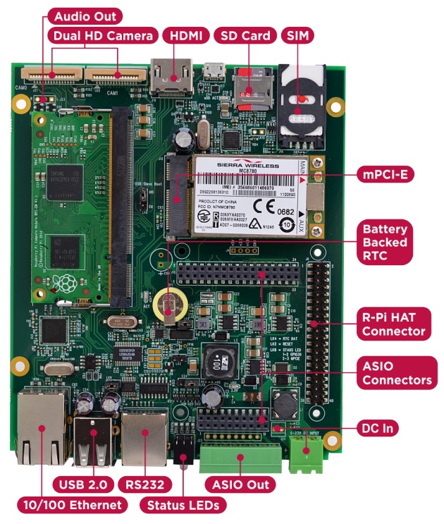
· Integrated 10/100 Ethernet Adapter
· Dual High-Resolution Raspberry Pi Camera Interfaces
· Mini PCI-E Interface + SIM connector
· High Speed SD compliant Micro SD Card interface
· ASIO Connectors allowing more comprehensive Application Specific solutions
· Raspberry Pi 2 HAT Compatible I/O Connector & Mounting Points (4 x M2.5)
· Independent USB UART (RX/TX/RTS/CTS)
· HDMI Out
· 8Way 2 part 3.5mm Phoenix industrial connector for use with ASIO Outputs or HAT board
· Integrated battery backed Real-Time-Clock (RTC)
· 2 x Bi-Colour (Red/Green) front panel status LEDs
· Wide 7-23V (poly-fused and filtered) High capacity DC power input via either 2 part Phoenix screw terminal front panel connector or internal 2way Molex AM254 Connector
HAT Compatible
Because the platform uses a standard HAT connector it's also backwards compatible with RPi HAT boards that you may already have or want to use, even allowing you to bring HAT IO connectivity out of the front using the industrial connector.
I/O Cards
In order to retain flexibility for various different IO configurations they have opted to use I/O connector in, instead of the actual I/O. So instead of plugging in HAT card with I/O signal connectors poking out on all sides, they have these same I/O signals back down a second output connector which is directly connected to the green industrial connector.
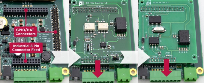
The added bonus here is that by simply using extended length interface pins on the card (raising it up) you can expand the IO set further - all without using any cable assemblies! They have pre-designed a series of hardened plug in cards for dealing common applications like CAN-Bus, 4-20mA transducer signals, RS485, Narrow Band RF and others. This way you have to spend less time dealing with hardware and more time focusing on software development.
Enclosure Design
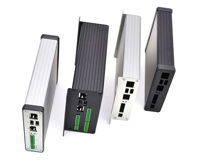
The best thing about their enclosure type is that they require only the end plates to be punched to match the board connectors, which reduces the design and manufacturing costs involved significantly. The PCB features 4 mounting holes, making it easy to install inside a larger or custom enclosure design if required.
The enclosure comes in two sizes, a low profile version and a larger double height model allowing extra room. All the single function I/O cards designed have been built with the lowest profile enclosure type in mind allowing for a neat solution.
Head over to Kickstarter to read more or to back the campaign.
Head over to Kickstarter to read more or to back the campaign.
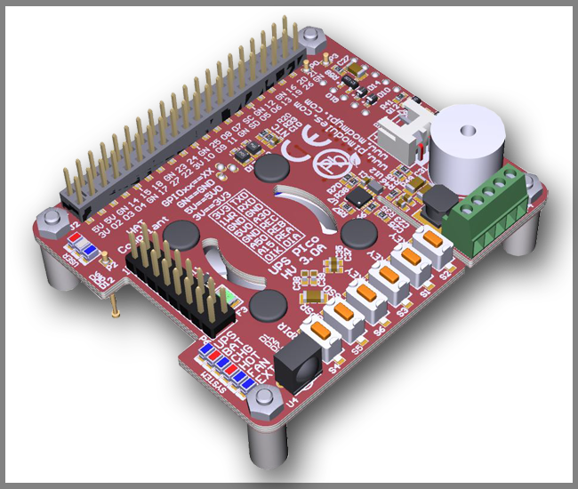
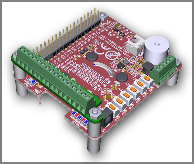
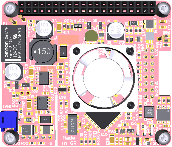
It is specially designed for the Raspberry Pi® 3 but it's also compatible with all other models. It comes equipped with 3 User Keys, 3 User LEDs, 3 different types of high capacity batteries, 2 x 3 pins bi-stable relay (Zero Power), as also 3 x A/D 12 bit converters pre-adjusted to 5V, 15V and 30V conversion.
Power Specifications:
Pimodules have implemented a Dynamic Power Tracking feature that can automatically adjust battery charging current according to power availability ranging from 50mA - 1000 mAh. This feature has been especially designed to support Solar Panel Powering Raspberry Pi® Systems, as the output from solar panel can vary according to weather conditions. UPS PIco HV3.0A can accept external voltage input ranging from 7 V DC up to 28 V DC !! This makes it ideal for use in Cars, Trucks, Buses and any industrial applications where voltage is usually higher than 24V DC. The External Supply Powering Input is equipped with Over Current protection, Over Voltage as also with Zero Voltage Drop Inverse Polarity Protection in order to use all available energy from the solar panel.
Product Overview:
The UPS PIco HV3.0A is equipped with a standard 450 mAh 15C LiPO battery specially designed to enable safe shutdown during mains power failure. The included battery provides enough power to keep running the system for 5-8 minutes. Additionally, you can also upgrade the battery capacity to 4000mAh, 8000 mAh or 12000 mAh batteries (optional on special request). With 12000 mAh batteries on board, you can use your Raspberry Pi for more than 32 hours without a power supply connected!
The UPS PIco HV3.0A 450 mAh Stack Plus design supports 2 types of lithium cell chemistry: LiPO as also LiFePO4. LiFePO4 batteries are useful in applications where temperature environment is more restricted which can range from -10 degrees up to +60 degrees. In addition, the LiFePO4 chemistry offers a longer cycle life than other lithium-ion cells out there. It can achieve up to 2000 cycles!!
Peripherals
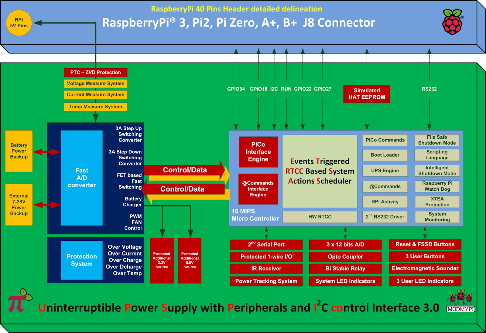
1. RTCC: UPS PIco HV3.0A comes with a integrated Hardware Real Time Clock and Calendar, which keeps time even when the system is running without access to the Network. The Hardware RTCC is backed up and powered from the integrated system battery. The RTCC current consumption is only 1 uA. The integrated Hardware RTCC enables a new extremely usefully feature - the Events Triggered RTCC Based System Actions Scheduler. The Events Triggered RTCC Based System Actions Scheduler allows to timely start up, or shutdown the Raspberry Pi® on various internal or external events that include, 1-wire, IR, A/D, RTCC, temperature, Opto Coupled Input or just on requested Time Stamp.
3. Monitoring: You can now monitor high voltage signals safely with the Opto Coupled interface, which can be read as digital or as analogue input. It's 12 bit buffered A/D comes with built-in ESD protection. In addition, you can monitor system health such as Battery Voltage, External Powering Voltage, Raspberry Pi Voltage, Current Consumption, System Temperature and 1-wire interface.
4. IR Receiver: The UPS PIco HV3.0A can also be equipped with an optional Infra-Red Receiver which is routed directly to GPIO18 via the PCB. This opens the door for remote operation of the Raspberry Pi® and UPS Pico!
5. Sound Transducer: The embedded Electromagnetic Programmable Sounder can be used as a simple buzzer but also as music player due to implemented sound generator and dedicated programmer interface.
6. Secondary Serial Port: With UPS PIco HV3.0A you can have access to a integrated secondary serial port which is compatible with both 3.3V & 5V TTL logic level. When used with Terminal Block it can support up-to 12V TTL logic level conversion. Their software driver is under development and will be delivered within 1 month after system delivery.
7. LEDS: UPS PIco HV3.0A comes with six independent LED's to inform user about system status.
Finally, the UPS PIco HV3.0A features an Automatic Temperature Control PWM FAN controller, and can be equipped with a micro fan kit, which enables the use of the Raspberry Pi® in extreme conditions including very high temperature environments. The FAN speed is automatically adjusted according to system temperature conditions semi linearly (8 levels) from 0 % (FAN is OFF) up to 100% by increasing and decreasing rotation speed. This guarantees a always cool Raspberry Pi® with low noise level.
Technical Specifications:
Product Comparison Table: UPS PIco HV3.0A_Product_Comparison.pdf
In this post I will demonstrate how you can utilize a modest PICAXE micro-controller as a multi channel ADC.We would be utilizing I2C bus to access the PICAXE, which will dump the values to memory registers.Your Pi must be configured to use the I2C bus.You can refer to this post for setting up I2C.
Very few PICAXEs can act as an I2C slave.One of them is 28X1. I have collected some fundamental information about PICAXEs, but in the event that you have never utilized one before, I suggest you to get basic knowledge about PICAXE's (Google is your friend ;) ).
You will require a minimum working circuit for PICAXe with power,reset and download socket to proceed.Here I am connecting 4 potentiometer with the ADC channel of PICAXE to demonstrate the working.

You will need to download the below code into your PICAXE. Values from ADC is dumped into the micro-controller's scratchpad memory which can be accessed via I2C bus.
#no_data
#no_table
hi2csetup i2cslave, 100000
main:
readadc 0,b1
readadc 1, b2
readadc 2, b3
readadc 3, b4
put 1, b1
put 2, b2
put 3, b3
put 4, b4
goto main
Code for Raspberry Pi:-
I have created a python script to access the PICAXE's scratchpad memory over I2C bus.It reads and displays the values.Save the script as read_adc.py.
import smbus
import time
bus=smbus.SMBus(0)
add=0x10
def read(reg):
value=bus.read_byte_data(add, reg)
return value
adc_channel1=0
adc_channel2=0
adc_channel3=0
adc_channel4=0
while True:
adc_channel1=read(1)
adc_channel2=read(2)
adc_channel3=read(3)
adc_channel4=read(4)
print adc_channel1
print adc_channel2
print adc_channel3
print adc_channel4
time.sleep(0.3)
Testing:-
Run the script on your pi as-
[email protected]:~# sudo python read_adc.py
It should now display the ADC values in your screen!
Warning:- Use a voltage level shifter ( 5V <----> 3.3V ) when interfacing the PICAXE with Raspberry Pi, as Pi cannot tolerate 5V!.
(Update):- If you have a Raspberry Pi with a revision 2.0 board, you need to use I²C bus 1, not bus 0, so you will need to change the bus number used. In this case, the line bus=smbus.SMBus(0) would become bus=smbus.SMBus(1).
You can check that the device is present on the bus by using the i2cdetect program from the i2ctools package-
i2cdetect 0 -y or i2cdetect 1 -y
Tutorial credit: AntMan232

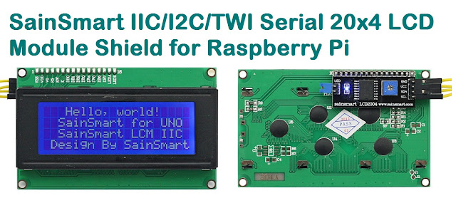
Hitachi HD44780 based 16x2 character LCD are very cheap and widely available, and is a essential part for any projects that displays information. Using the I2C bus on Raspberry Pi ,PCF8574 IC, and Python characters/strings can be displayed on the LCD. The PCF8574 is an general purpose bidirectional 8 bit I/O port expander that uses the I2C protocol.
The LCD(HD44780) is connected in 4 bit mode as follows to the PCF8574:-

P0 - D4
P1 - D5
P2 - D6
P3 - D7
P4 - RS
P5 - R/W
P6 - E
Port A0 is connected to VCC(5V) with a 10k resistor so that it will be addressed at 0x21.


import smbus
from time import *
# General i2c device class so that other devices can be added easily
class i2c_device:
 def __init__(self, addr, port):
  self.addr = addr
  self.bus = smbus.SMBus(port)
 def write(self, byte):
  self.bus.write_byte(self.addr, byte)
 def read(self):
  return self.bus.read_byte(self.addr)
 def read_nbytes_data(self, data, n): # For sequential reads > 1 byte
  return self.bus.read_i2c_block_data(self.addr, data, n)
class lcd:
 #initializes objects and lcd
 '''
 Reverse Codes:
 0: lower 4 bits of expander are commands bits
 1: top 4 bits of expander are commands bits AND P0-4 P1-5 P2-6
 2: top 4 bits of expander are commands bits AND P0-6 P1-5 P2-4
 '''
 def __init__(self, addr, port, reverse=0):
  self.reverse = reverse
  self.lcd_device = i2c_device(addr, port)
  if self.reverse:
   self.lcd_device.write(0x30)
   self.lcd_strobe()
   sleep(0.0005)
   self.lcd_strobe()
   sleep(0.0005)
   self.lcd_strobe()
   sleep(0.0005)
   self.lcd_device.write(0x20)
   self.lcd_strobe()
   sleep(0.0005)
  else:
   self.lcd_device.write(0x03)
   self.lcd_strobe()
   sleep(0.0005)
   self.lcd_strobe()
   sleep(0.0005)
   self.lcd_strobe()
   sleep(0.0005)
   self.lcd_device.write(0x02)
   self.lcd_strobe()
   sleep(0.0005)
  self.lcd_write(0x28)
  self.lcd_write(0x08)
  self.lcd_write(0x01)
  self.lcd_write(0x06)
  self.lcd_write(0x0C)
  self.lcd_write(0x0F)
 # clocks EN to latch command
 def lcd_strobe(self):
  if self.reverse == 1:
   self.lcd_device.write((self.lcd_device.read() | 0x04))
   self.lcd_device.write((self.lcd_device.read() & 0xFB))
  if self.reverse == 2:
   self.lcd_device.write((self.lcd_device.read() | 0x01))
   self.lcd_device.write((self.lcd_device.read() & 0xFE))
  else:
   self.lcd_device.write((self.lcd_device.read() | 0x10))
   self.lcd_device.write((self.lcd_device.read() & 0xEF))
 # write a command to lcd
 def lcd_write(self, cmd):
  if self.reverse:
   self.lcd_device.write((cmd >> 4)<<4 0x0f="" cmd="" else:="" self.lcd_device.write="" self.lcd_strobe="" x0="">> 4))
   self.lcd_strobe()
   self.lcd_device.write((cmd & 0x0F))
   self.lcd_strobe()
   self.lcd_device.write(0x0)
 # write a character to lcd (or character rom)
 def lcd_write_char(self, charvalue):
  if self.reverse == 1:
   self.lcd_device.write((0x01 | (charvalue >> 4)<<4 0x0f="" 2:="" charvalue="" if="" self.lcd_device.write="" self.lcd_strobe="" self.reverse="=" x01="" x04="" x0="">> 4)<<4 0x0f="" charvalue="" else:="" self.lcd_device.write="" self.lcd_strobe="" x04="" x0="" x40="">> 4)))
   self.lcd_strobe()
   self.lcd_device.write((0x40 | (charvalue & 0x0F)))
   self.lcd_strobe()
   self.lcd_device.write(0x0)
 # put char function
 def lcd_putc(self, char):
  self.lcd_write_char(ord(char))
 # put string function
 def lcd_puts(self, string, line):
  if line == 1:
   self.lcd_write(0x80)
  if line == 2:
   self.lcd_write(0xC0)
  if line == 3:
   self.lcd_write(0x94)
  if line == 4:
   self.lcd_write(0xD4)
  for char in string:
   self.lcd_putc(char)
 # clear lcd and set to home
 def lcd_clear(self):
  self.lcd_write(0x1)
  self.lcd_write(0x2)
 # add custom characters (0 - 7)
 def lcd_load_custon_chars(self, fontdata):
  self.lcd_device.bus.write(0x40);
  for char in fontdata:
   for line in char:
    self.lcd_write_char(line)
Main Program:-
import pylcdlib
lcd = pylcdlib.lcd(0x21,0)
lcd.lcd_puts("Raspberry Pi",1)  #display "Raspberry Pi" on line 1
lcd.lcd_puts("  Take a byte!",2)  #display "Take a byte!" on line 2
Save the above code as test_lcd.py and enter sudo python test_lcd.py
My code assumes that the first 4 bits of the LCD(11,12,13,14) are connected to P0,P1,P2,P3 ports on PCF8574. The next 3 ports on PCF8574(P4,P5,P6) should be connected to 4-RS, 5-R/W, 6-E.However there are other serial backpack lcd's with different pinouts. According to the wiring of your serial backpack LCD you can override the default mapping during initialization.There are 3 modes available-
lcd = pylcdlib.lcd(0x21,0) lower 4 bits of expander are commands bits
lcd = pylcdlib.lcd(0x21,0,1) top 4 bits of expander are commands bits AND P0-4 P1-5 P2-6
lcd = pylcdlib.lcd(0x21,0,2) top 4 bits of expander are commands bits AND P0-6 P1-5 P2-4
(Update):- If you have a Raspberry Pi with a revision 2.0 board, you need to use I²C bus 1, not bus 0, so you will need to change the bus number used. In this case, the line lcd = pylcdlib.lcd(0x21,0) would become lcd = pylcdlib.lcd(0x21,1).
You can check that the device is present on the bus by using the i2cdetect program from the i2ctools package-
i2cdetect 0 -y or i2cdetect 1 -y
Compatible LCD Module for this article:-
The TMP102 is an I2C temperature sensor from Texas Instruments.It's a perfect sensor for Raspberry Pi as it lacks any onboard ADC and TMP102 eliminates the requirement for analyzing the analog signals.When compared with the analog sensors TMP102 is very accurate and capable of measuring 0.0625ºC changes between -25°C and +85°C.

If you have more than one device on the I2C bus you can modify the address of the sensor using the address pin (ADD0).The sensor's address will be 72(0×48 in hex) when the address pin is grounded.It will be set to 73 (0×49 in hex) if the address pin is tied to VCC.
Pi GPI0 Function
---------------------------
Pin 2 SDA
Pin 3 SCL
Pin 26 5V
Make sure your system has the latest version of Linux 3.2 kernel and a proper I2C driver.Also you will be requiring two utilities:-
1) "lm-sensors" package, enter "apt-get install lm-sensors"
2) "I2C tools" package, enter "apt-get install i2c-tools"
After installation we can now use the modprobe i2c-tools.Run "i2cdetect" to check whether TMP102 is connected.
[email protected]:~# i2cdetect -y 0
0 1 2 3 4 5 6 7 8 9 a b c d e f
00: -- -- -- -- -- -- -- -- -- -- -- -- --
10: -- -- -- -- -- -- -- -- -- -- -- -- -- -- -- --
20: -- -- -- -- -- -- -- -- -- -- -- -- -- -- -- --
30: -- -- -- -- -- -- -- -- -- -- -- -- -- -- -- --
40: -- -- -- -- -- -- -- -- 48 -- -- -- -- -- -- --
50: -- -- -- -- -- -- -- -- -- -- -- -- -- -- -- --
60: -- -- -- -- -- -- -- -- -- -- -- -- -- -- -- --
70: -- -- -- -- -- -- -- --
As we have received the address from i2cdetect, the system has to be updated to get new drivers.
[email protected]:~# echo tmp102 0x48 > /sys/class/i2c-adapter/i2c-0/new_device
Run the "sensors" command to get the temperature:-
[email protected]:~# sensors
tmp102-i2c-0-48
Adapter: bcm2708_i2c.0
temp1: +35.7°C (high = +70.0°C, hyst = +55.0°C)

(Update):- If you have a Raspberry Pi with a revision 2.0 board, you need to use I²C bus 1, not bus 0.You can check that the device is present on the bus by using the i2cdetect program from the i2ctools package:-
i2cdetect 0 -y or i2cdetect 1 -y
